foostan's Corne Keyboard (crkbd v3)
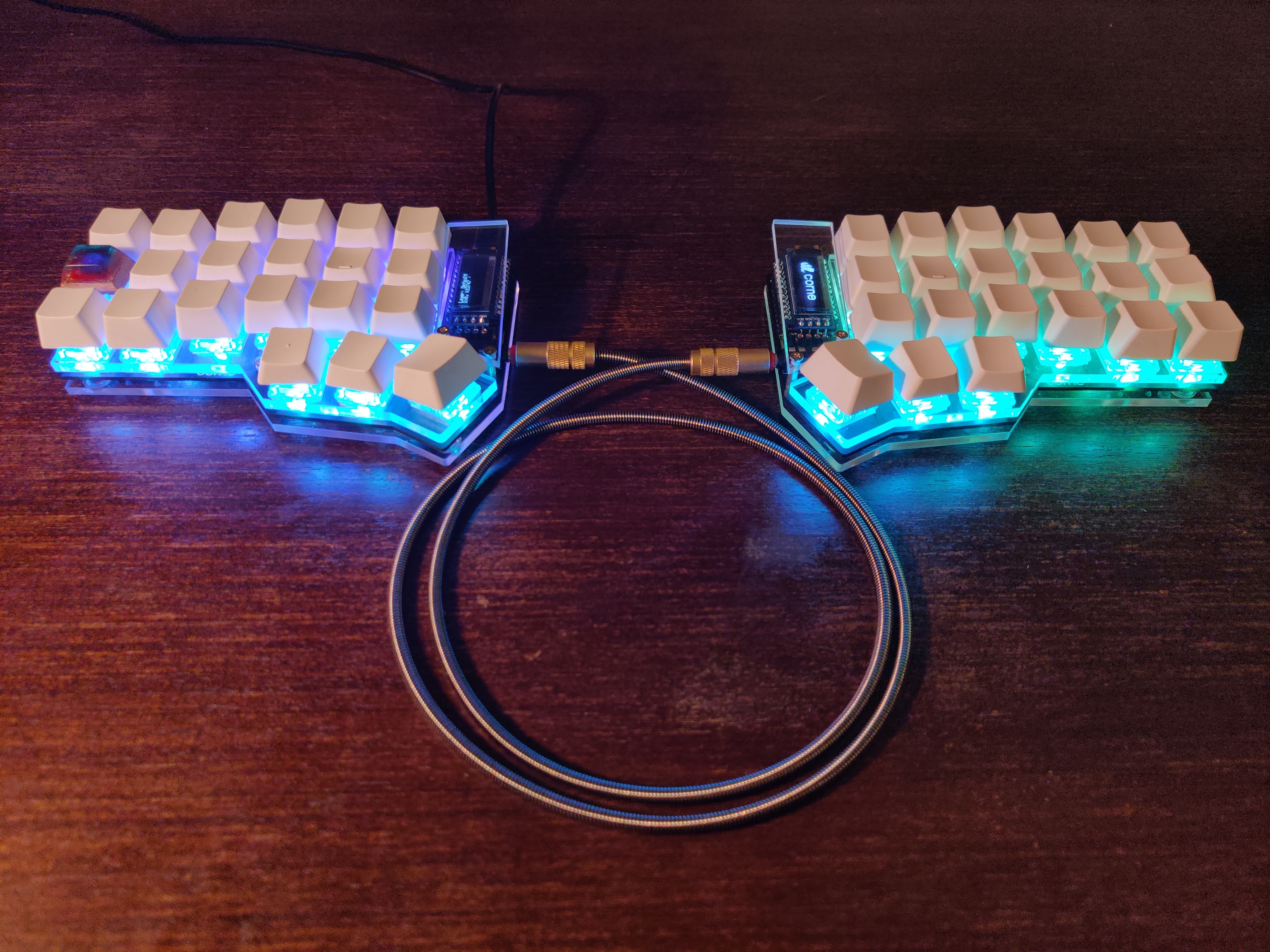
Check the final product
Check the video of this build
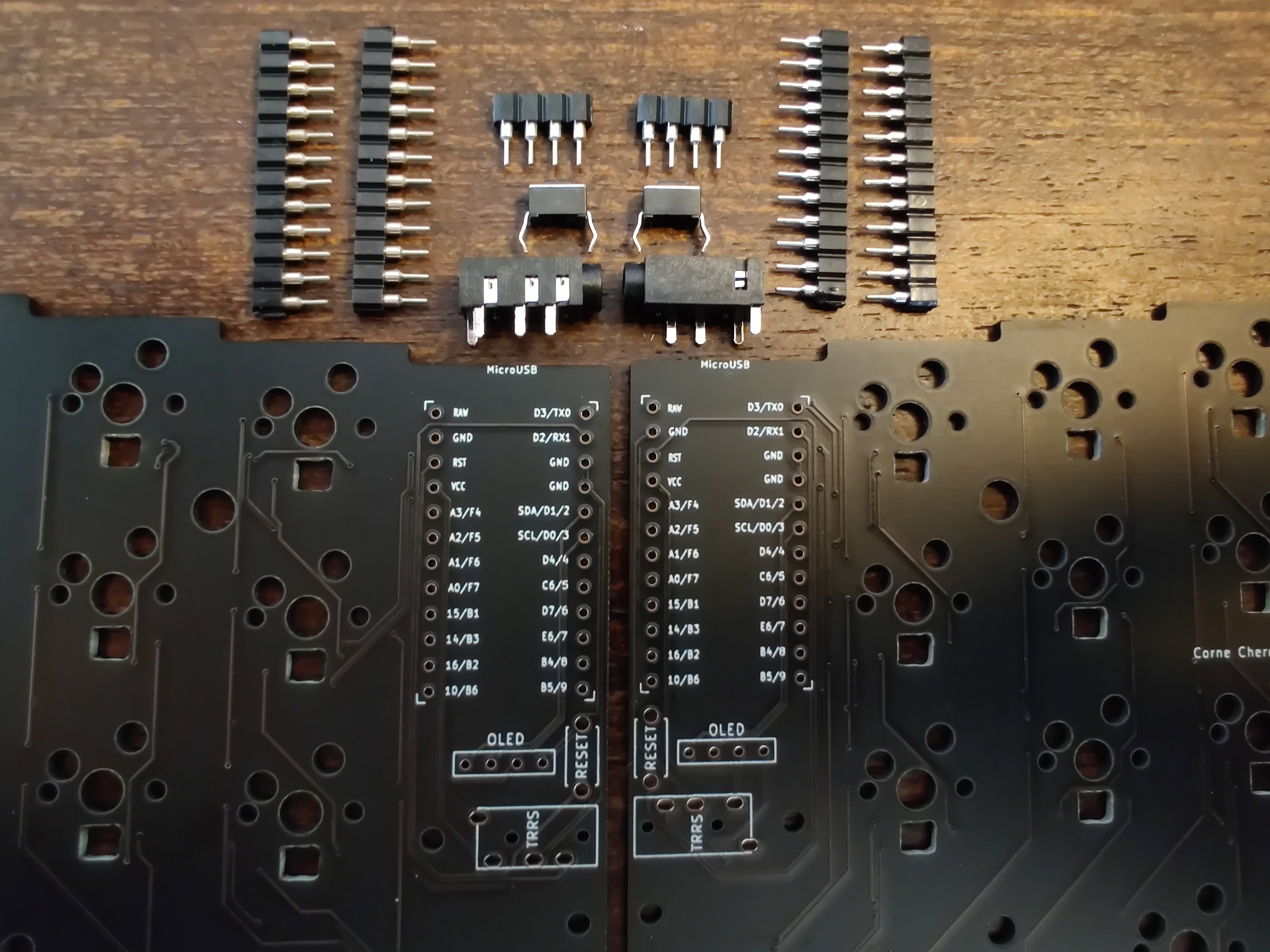
- Sort the parts
- Ordering the PCB
- Install/Configure QMK
- Compile/Flash Firmware
- Prepare the OLEDS
- Prepare the PCB
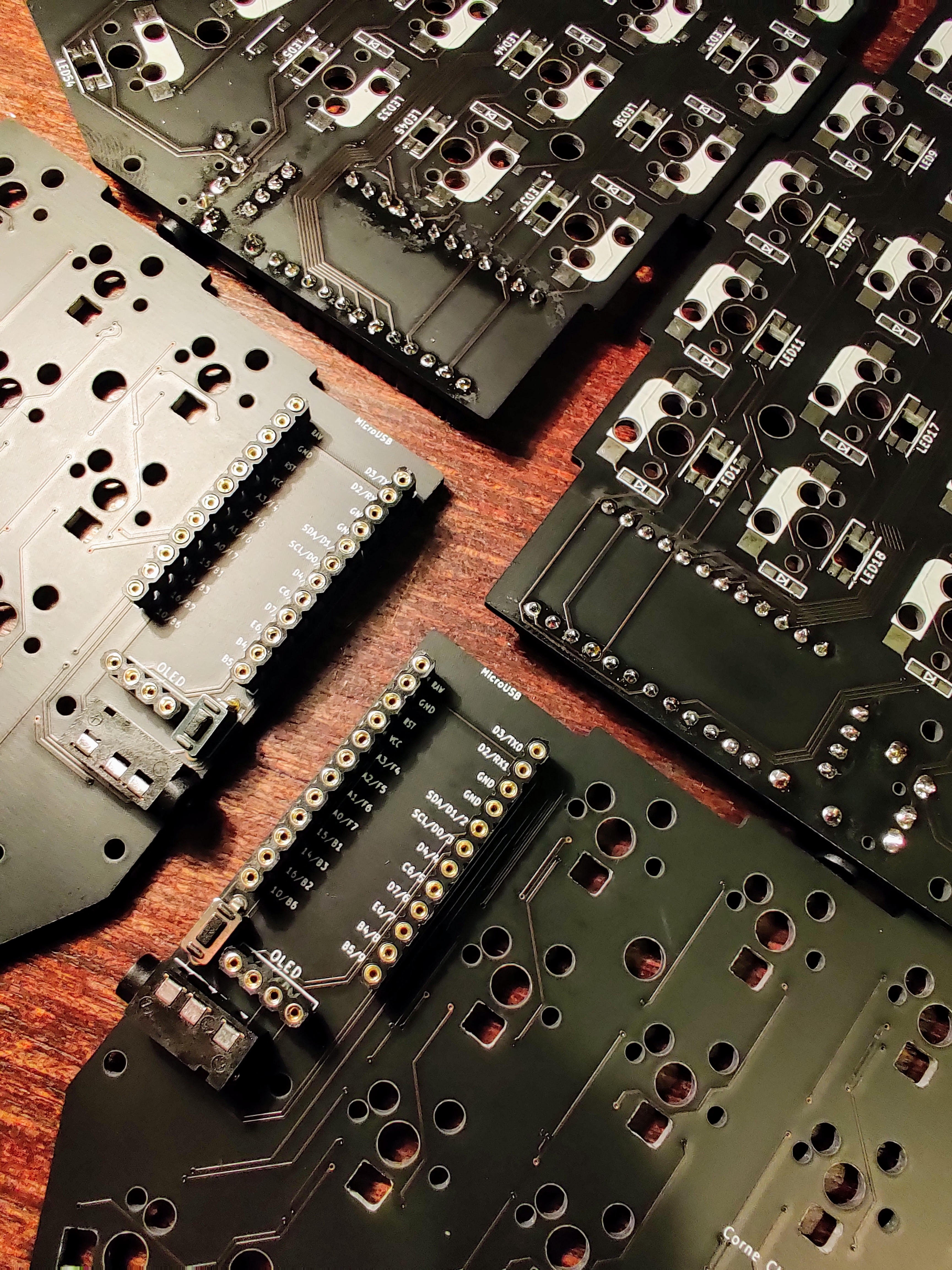
- Solder PCB top components
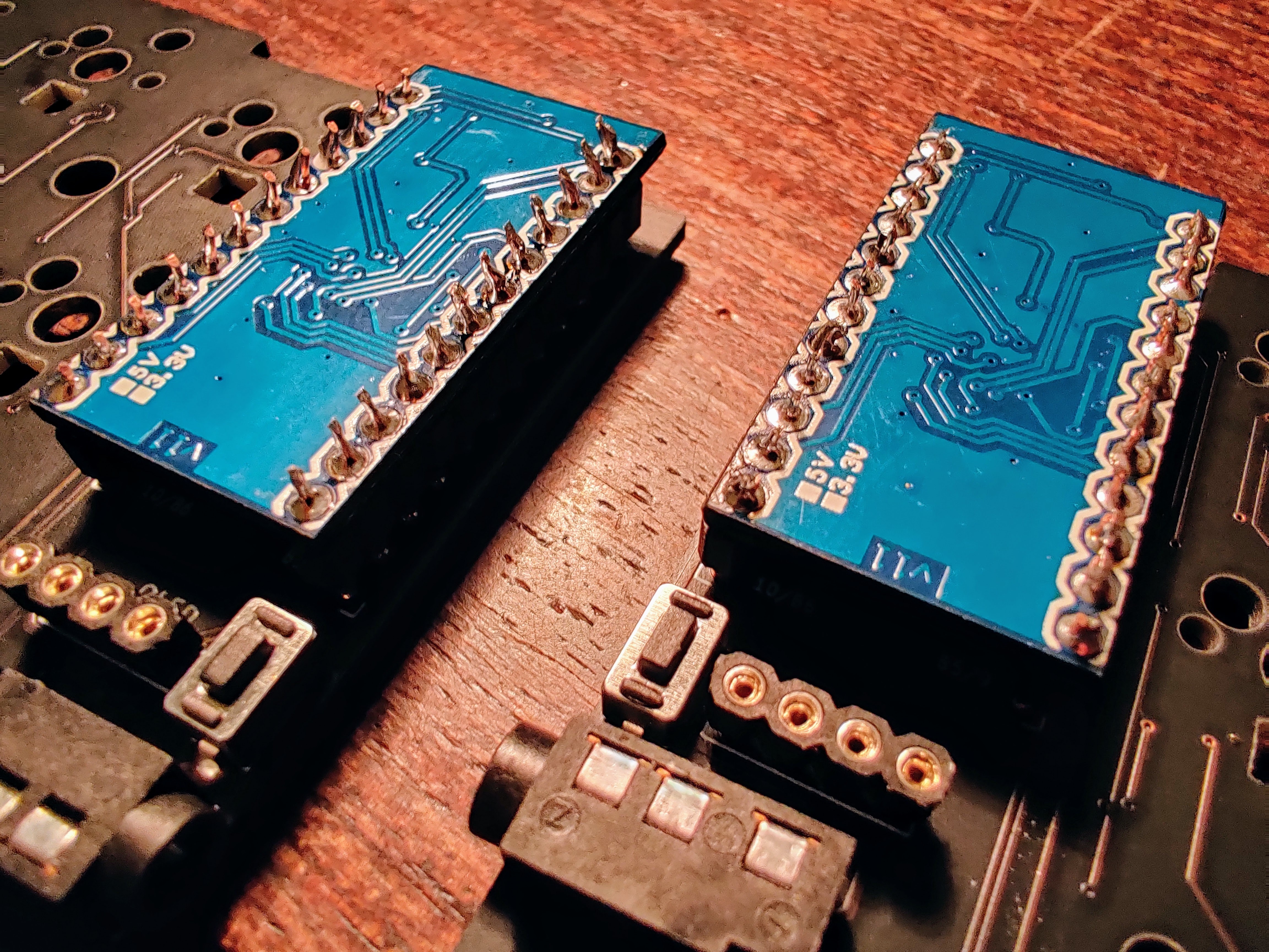
- Solder pro-micro
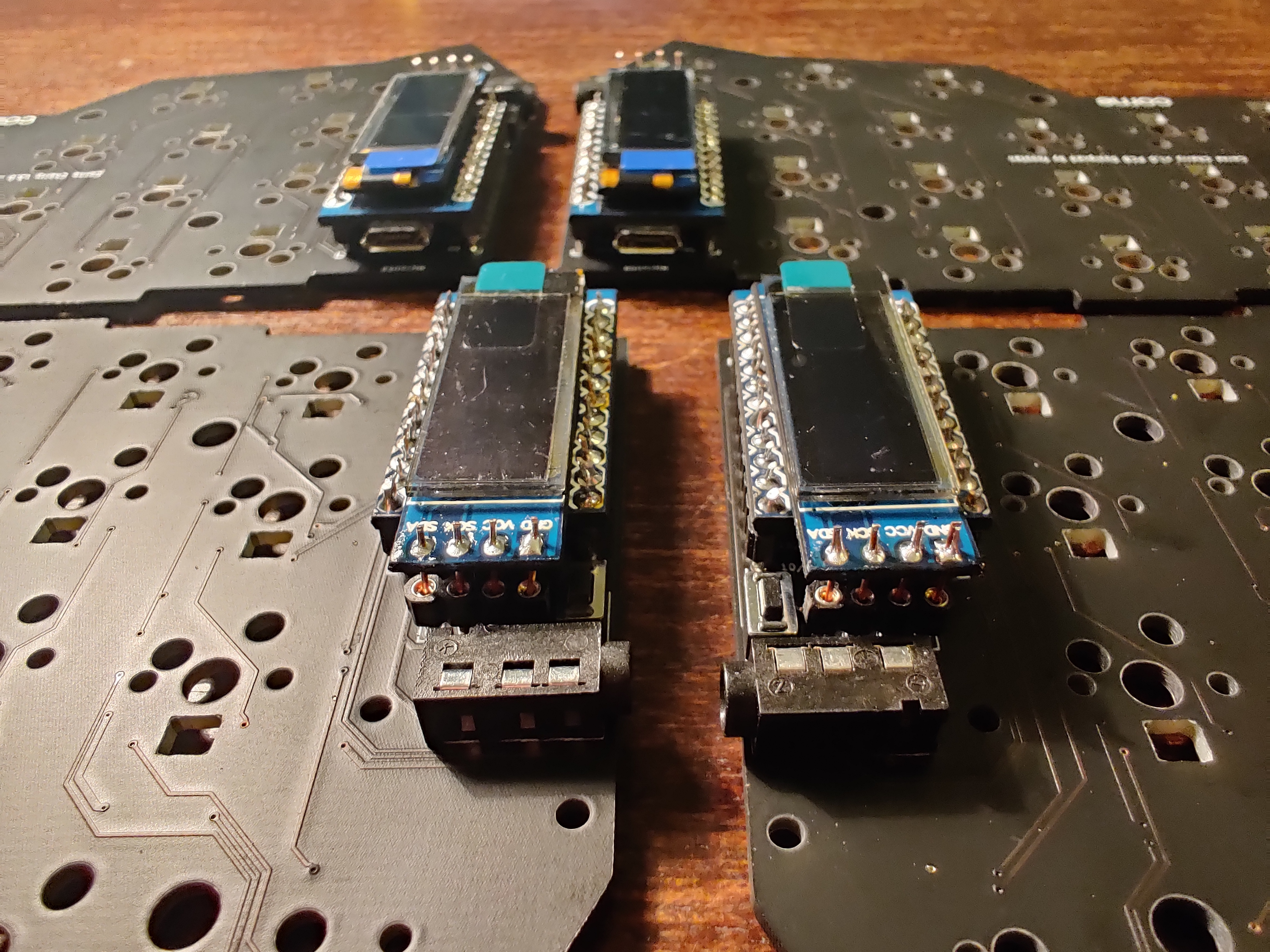
- Solder OLEDs
- Solder diodes
- Solder hot-swaps
- Solder under-glow leds
- Solder per-key leds
- Mount the case
Part list (Original)
- 1x Corne PCBs Printed mine on jlcpcb
- 1x Corne Case Laser cut mine on Brazil
- 42x Keycaps - 1u x 40, 1.5u x 2
- 2x Pro Micro ATmega32U4 5V/16MHz Module controller Mega32U4 Mini leonardo for Arduino with the bootloader
- 2x OLED 128X32 OLED Display Module 0.91" IIC Communicate for ardunio
- 42x Kailh Hot-swappable PCB Socket Sip For Mechanical Keyboard
- 42x SMD diodes 1N4148 SOD-123
- 1M Round Copper Wire 0.5mm
- 4x 2.54mm Pin Header Female Single Row 40
- 2x PJ320D 3.5MM Headphone TRRS Jack Socket Female Connector
- 1x 1m 4 pole Stero audio cable Car AUX MP3/MP4 3.5mm male to male
- 2x Micro Switch Push Button 3.5X6.0X4.3mm 1136-4.3 DIP Black
- 42x Holy Pandas switches
- 24x Screws M2 6mm
- 10x Spacers M2 7mm
- 4x Spacers M2 10mm
- 42x Leds SK6812-mini-E
- 12x Leds ws2812b
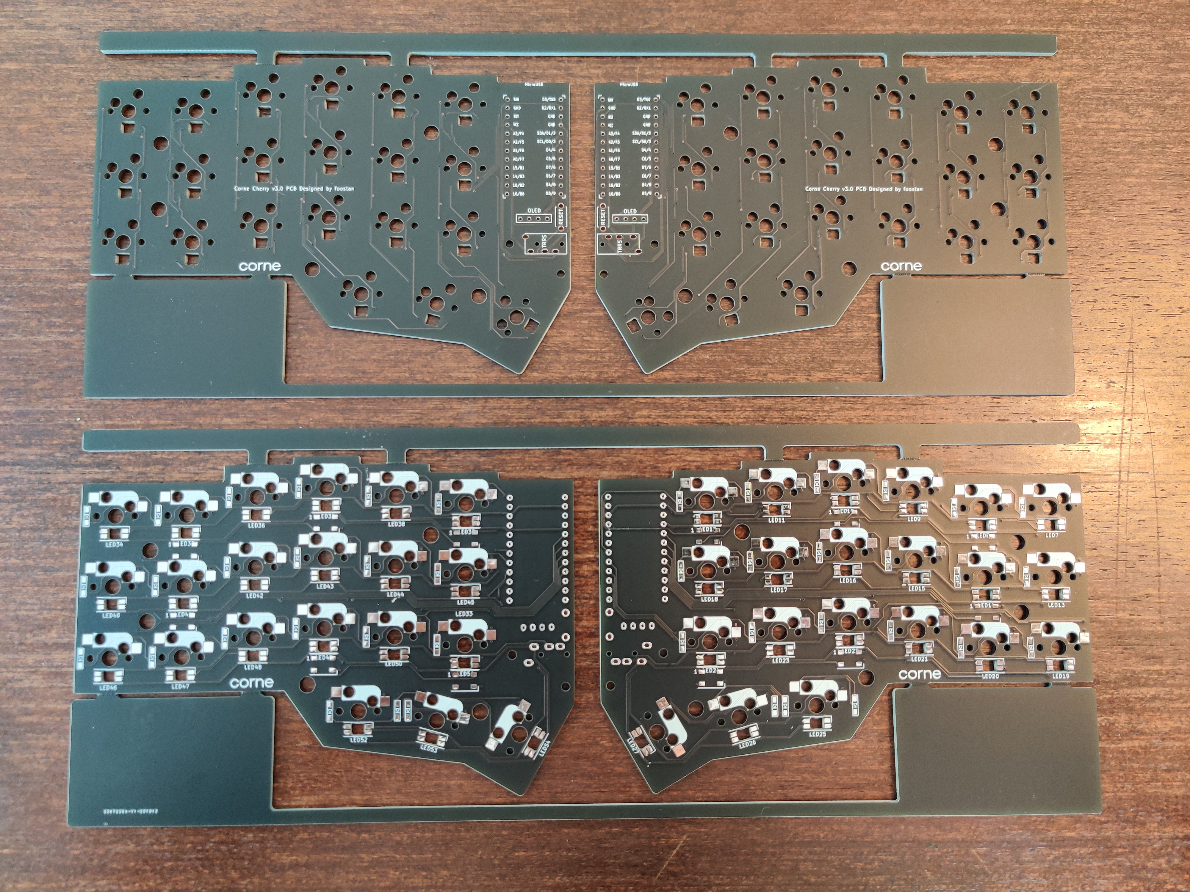
As you can see I pretty much uploaded the latest cherry gerber file avalilable on foostan's repository in https://jlcpcb.com and let almost all defaults settings.
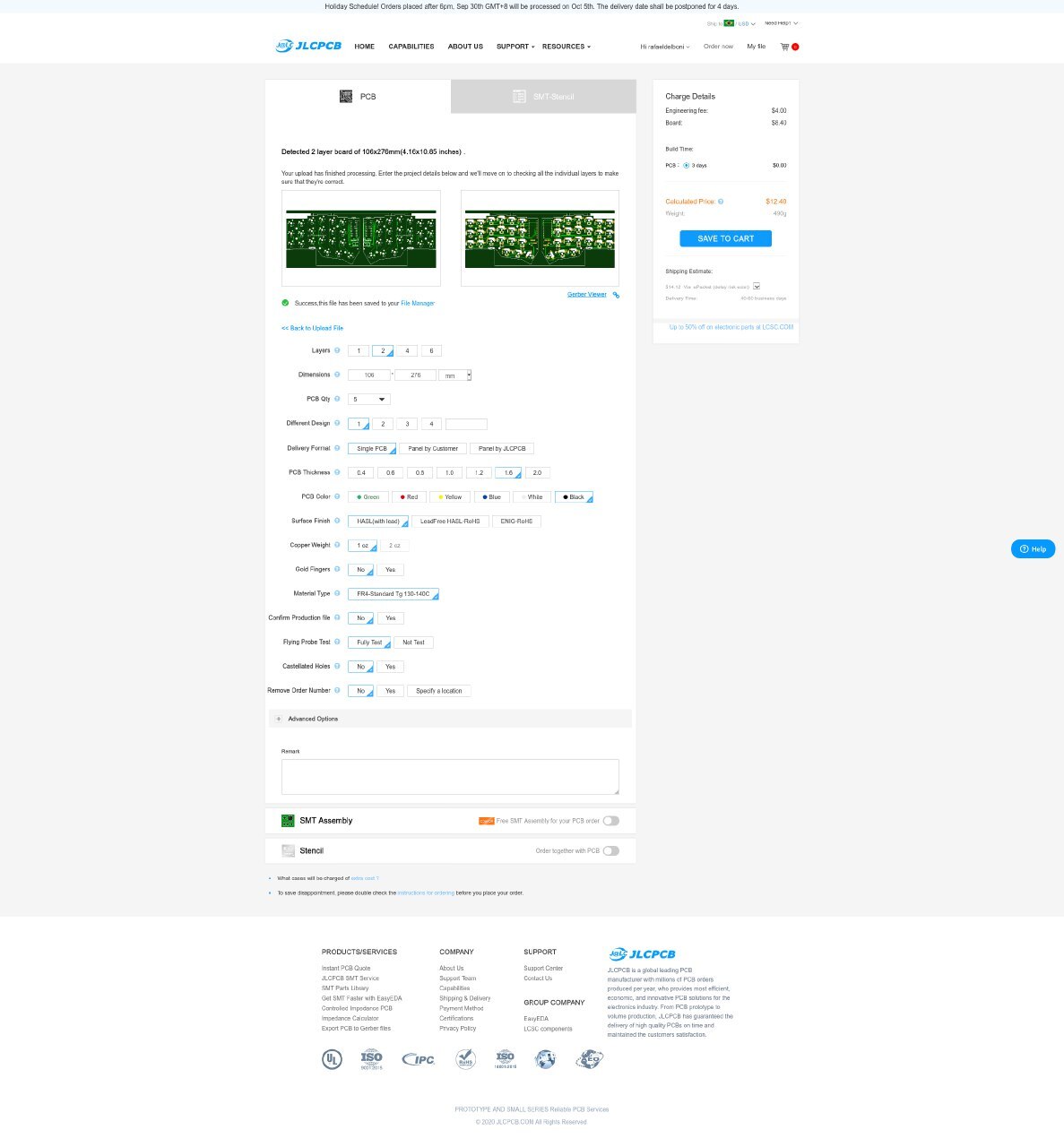 After a day I placed the order they sent me an email asking for an extra U$ 4.00,
 I didn't understand what happened, but I just paid it and everything worked fine. @Soziapath sent me an email explaining that the extra fee may occur if the jlcpcb reviwer understand that your gerber file had two different pcb's (mirrored is still different). More details
First to compile the crkbd qmk firmware you will need to use avr-gcc 8.
In Arch use the following commands to install the dependencies:
sudo pacman --needed -U https://archive.archlinux.org/packages/a/avr-gcc/avr-gcc-8.3.0-1-x86_64.pkg.tar.xz
sudo pacman -S --needed \
       arm-none-eabi-binutils \
       arm-none-eabi-gcc \
       arm-none-eabi-newlib \
       avrdude \
       avr-binutils \
       avr-libc \
       base-devel \
       clang \
       dfu-programmer \
       dfu-util \
       diffutils \
       gcc \
       git \
       libusb-compat \
       python \
       python-pip \
       unzip \
       wget \
       zip
Then clone the qmk firmware and then
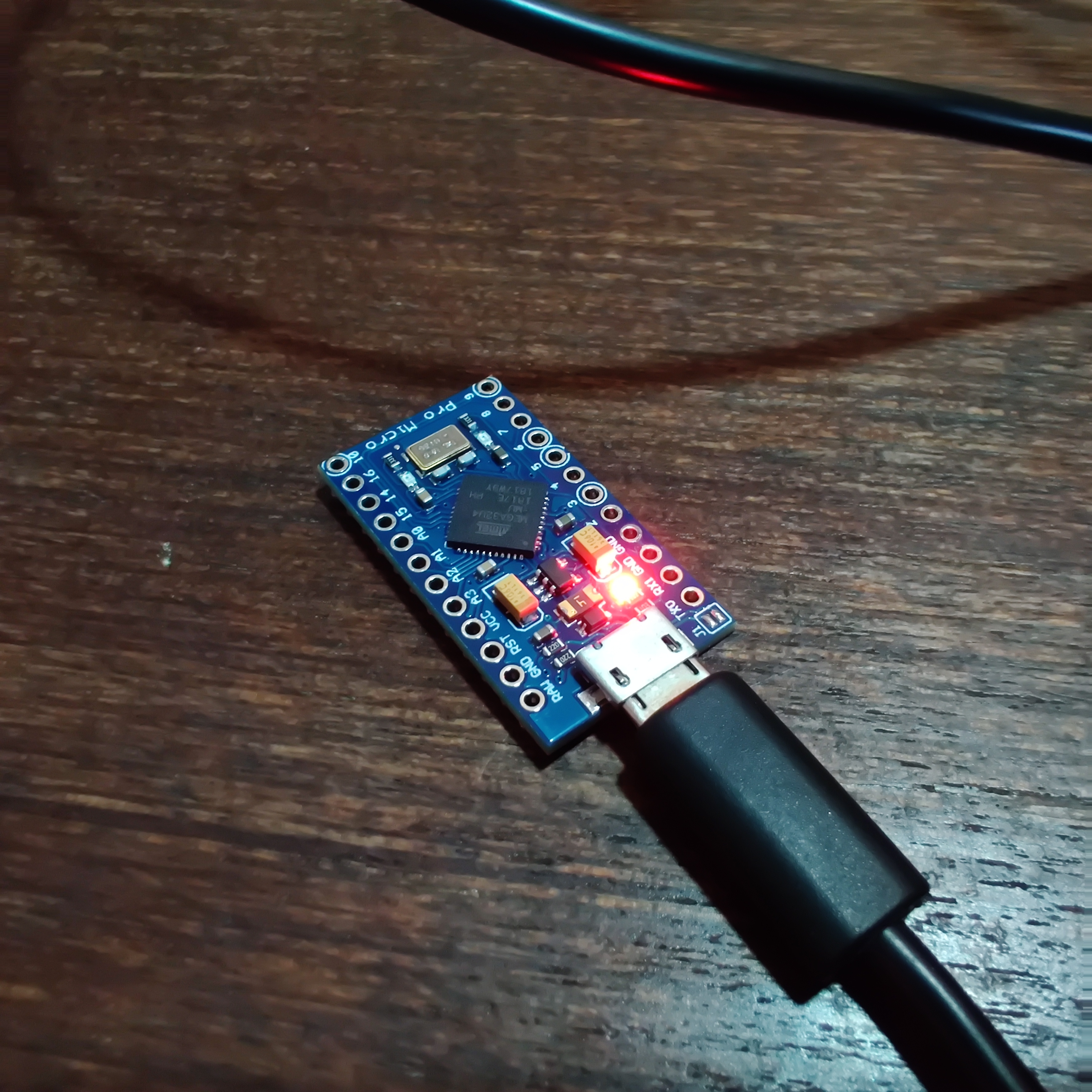
make crkbd:default:flashThis will compile and start to flash the firmware, make sure your pro-micro is connected in the usb port and the following message will be shown:
QMK Firmware 0.9.19
WARNING:
 Can not run bin/qmk! This tool will be required when the develop branch is merged on 2020 Aug 29.

 Please run util/qmk_install.sh to install all the dependencies QMK requires.

Making crkbd/rev1 with keymap default and target flash

avr-gcc (GCC) 8.3.0
Copyright (C) 2018 Free Software Foundation, Inc.
This is free software; see the source for copying conditions.  There is NO
warranty; not even for MERCHANTABILITY or FITNESS FOR A PARTICULAR PURPOSE.

Size before:
   text    data     bss     dec     hex filename
      0   21574       0   21574    5446 .build/crkbd_rev1_default.hex

Copying crkbd_rev1_default.hex to qmk_firmware folder                                               [OK]
Checking file size of crkbd_rev1_default.hex                                                        [OK]
 * The firmware size is fine - 21574/28672 (75%, 7098 bytes free)
Detecting USB port, reset your controller now..................
At this moment, with some tweezers, reset the pro-micro
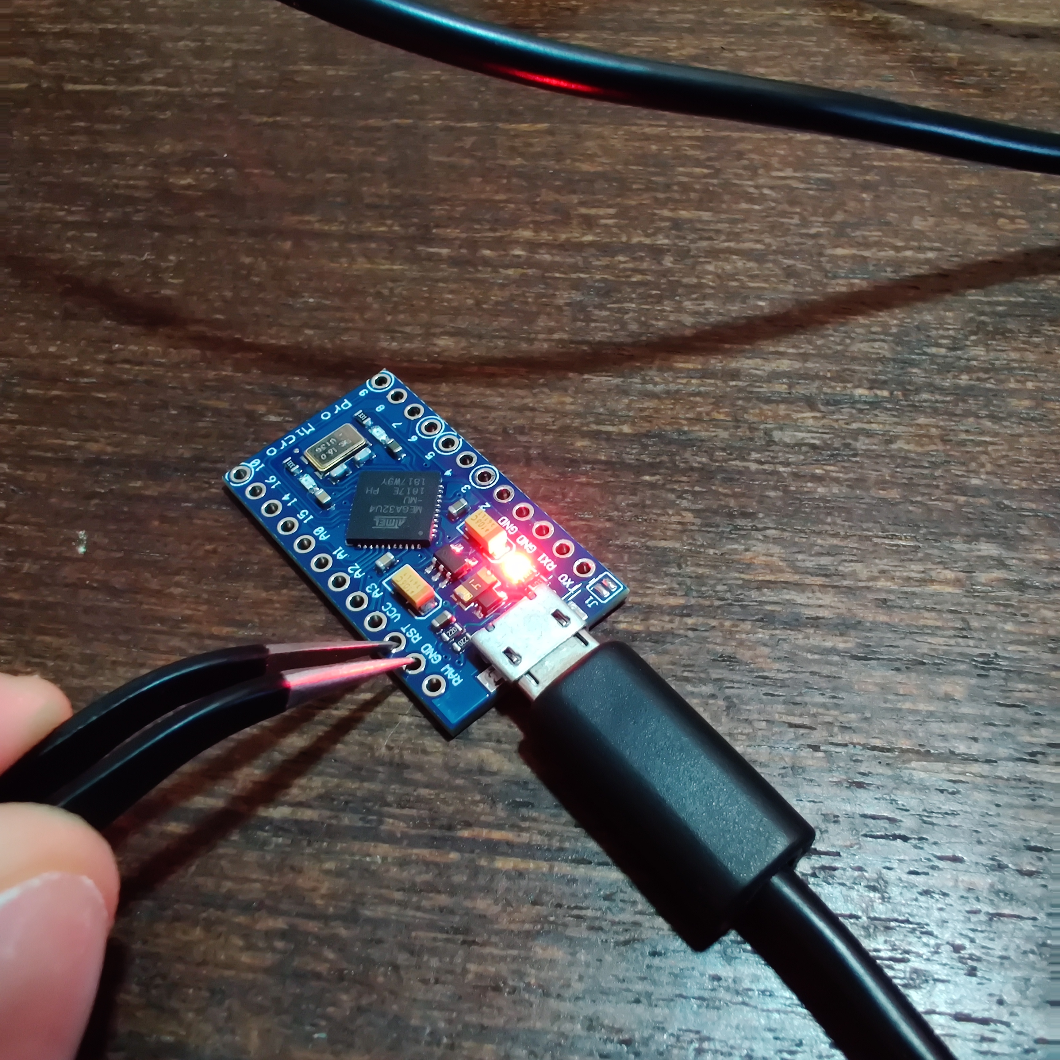
If you did right the following will be shown:
Device /dev/ttyACM0 has appeared; assuming it is the controller.
Waiting for /dev/ttyACM0 to become writable..

Connecting to programmer: .
Found programmer: Id = "CATERIN"; type = S
    Software Version = 1.0; No Hardware Version given.
Programmer supports auto addr increment.
Programmer supports buffered memory access with buffersize=128 bytes.

Programmer supports the following devices:
    Device code: 0x44

avrdude: AVR device initialized and ready to accept instructions

Reading | ################################################## | 100% 0.00s

avrdude: Device signature = 0x1e9587 (probably m32u4)
avrdude: NOTE: "flash" memory has been specified, an erase cycle will be performed
         To disable this feature, specify the -D option.
avrdude: erasing chip
avrdude: reading input file ".build/crkbd_rev1_default.hex"
avrdude: input file .build/crkbd_rev1_default.hex auto detected as Intel Hex
avrdude: writing flash (21574 bytes):

Writing | ################################################## | 100% 1.64s

avrdude: 21574 bytes of flash written
avrdude: verifying flash memory against .build/crkbd_rev1_default.hex:
avrdude: load data flash data from input file .build/crkbd_rev1_default.hex:
avrdude: input file .build/crkbd_rev1_default.hex auto detected as Intel Hex
avrdude: input file .build/crkbd_rev1_default.hex contains 21574 bytes
avrdude: reading on-chip flash data:

Reading | ################################################## | 100% 0.16s

avrdude: verifying ...
avrdude: 21574 bytes of flash verified

avrdude: safemode: Fuses OK (E:CB, H:D8, L:FF)

avrdude done.  Thank you.
Do this for both pro-micros and you good to go.
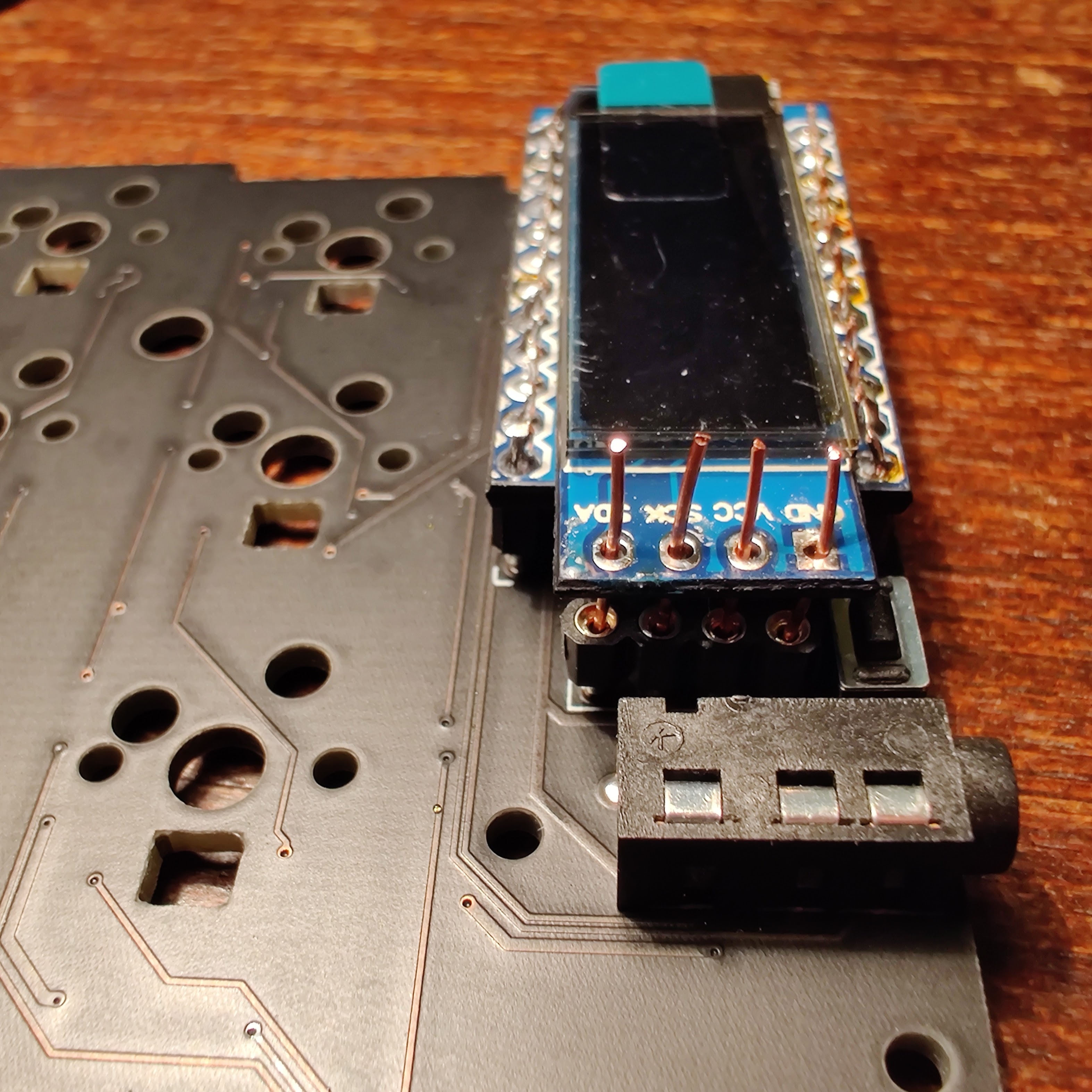
Remove the oleds legs for socketing can be quite challenging, I lost some oleds during this phase.
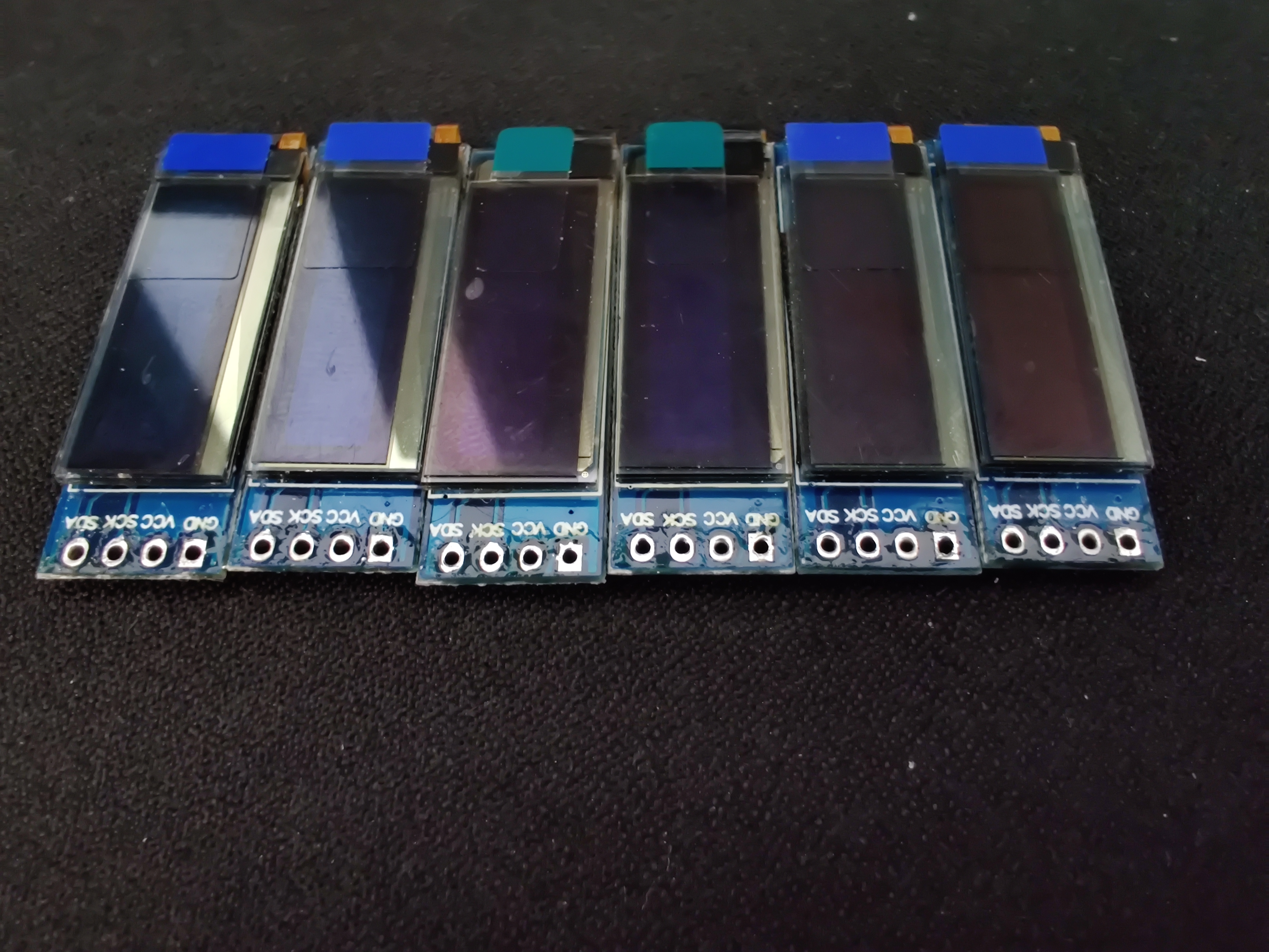
Those conections are ugly let's trim them out.
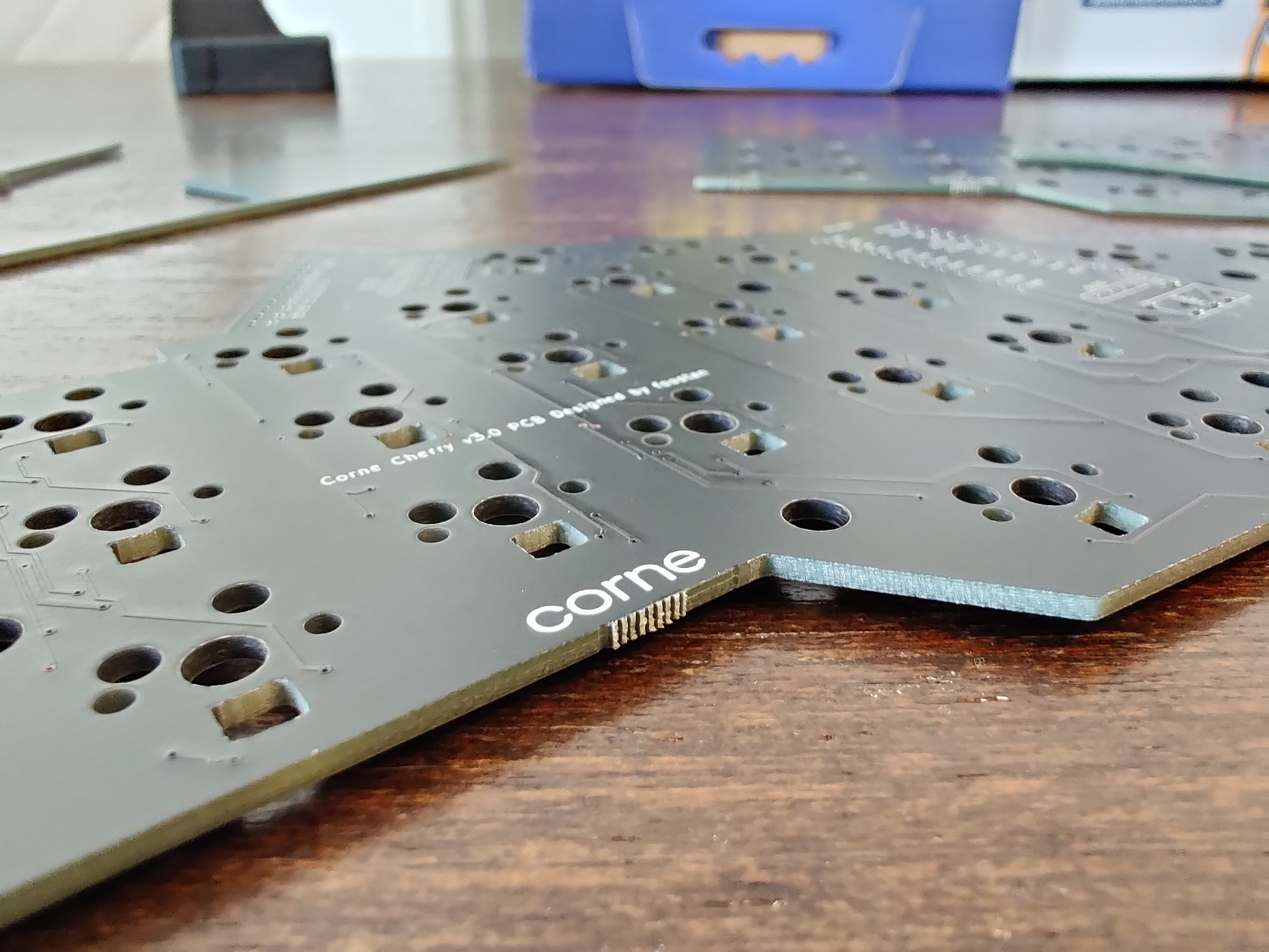
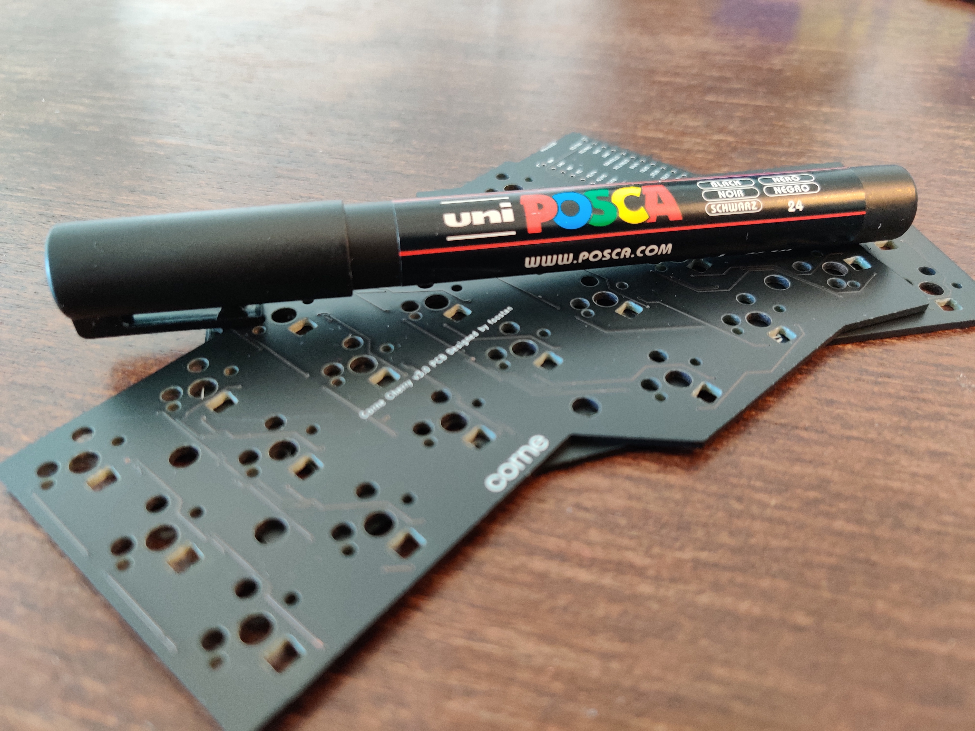
I like to paint the sides of the pcb to have a better finish.
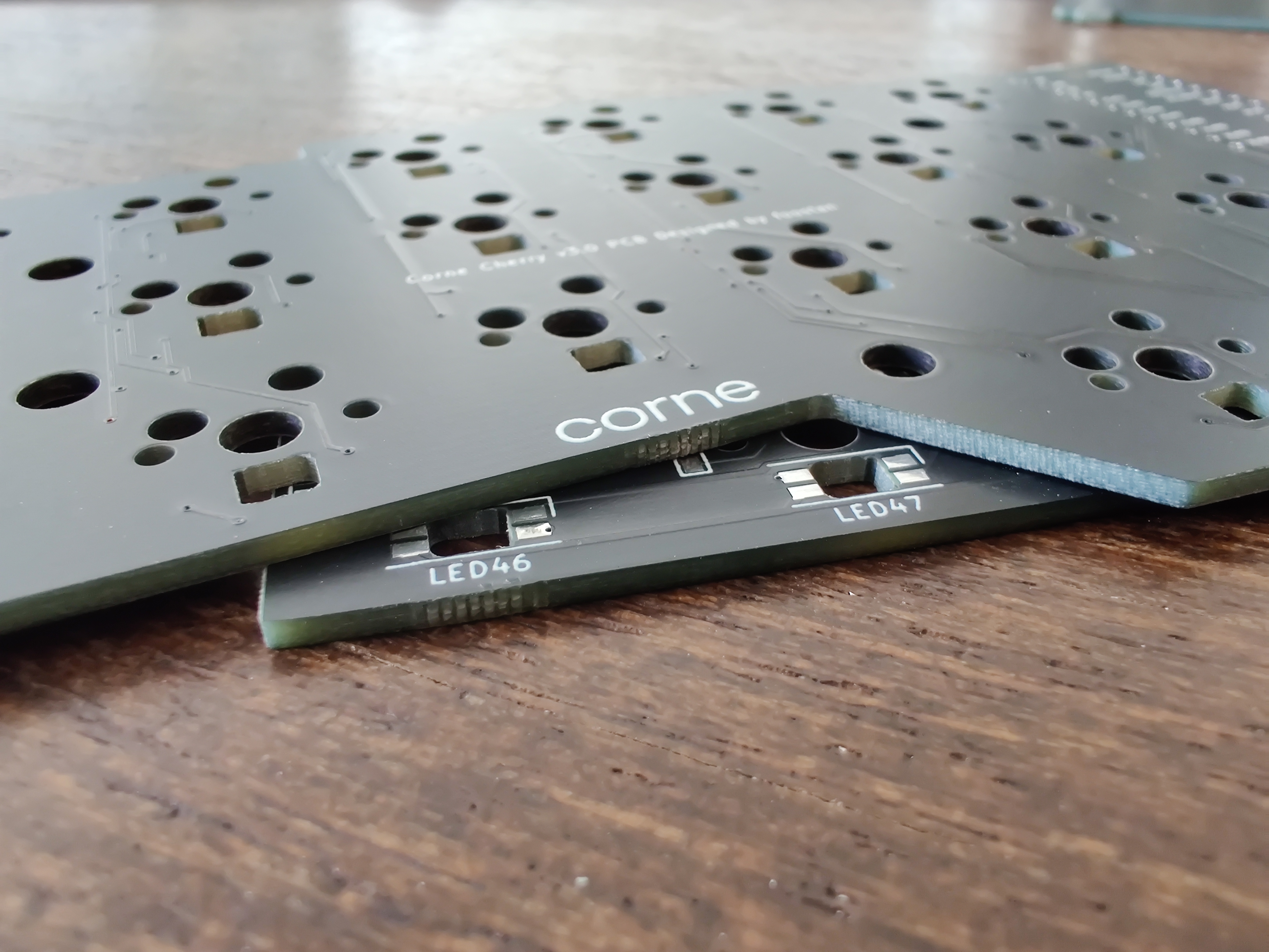
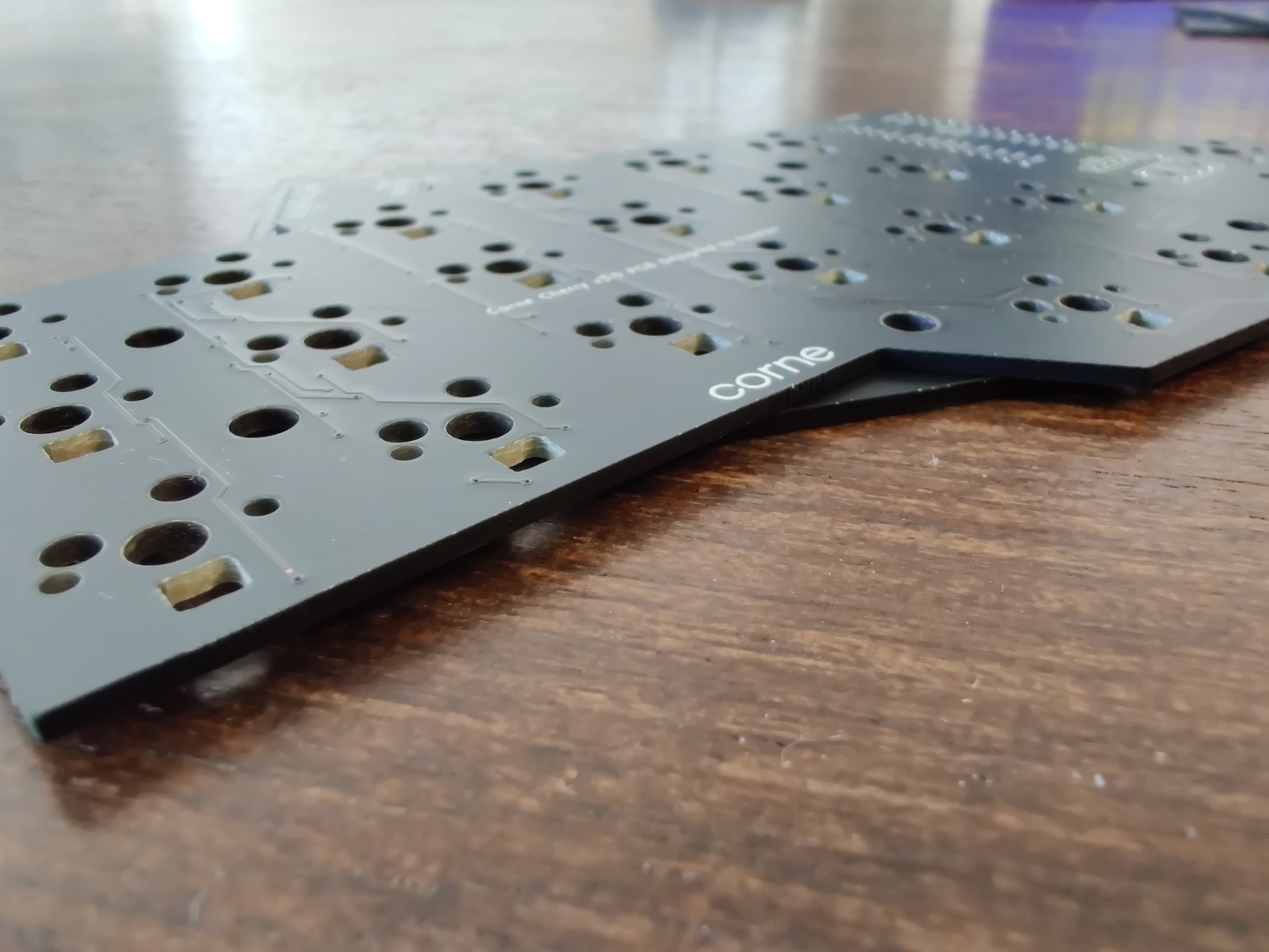
I used POSCA for painting the pcb sides.
I used some masking tape to help me.
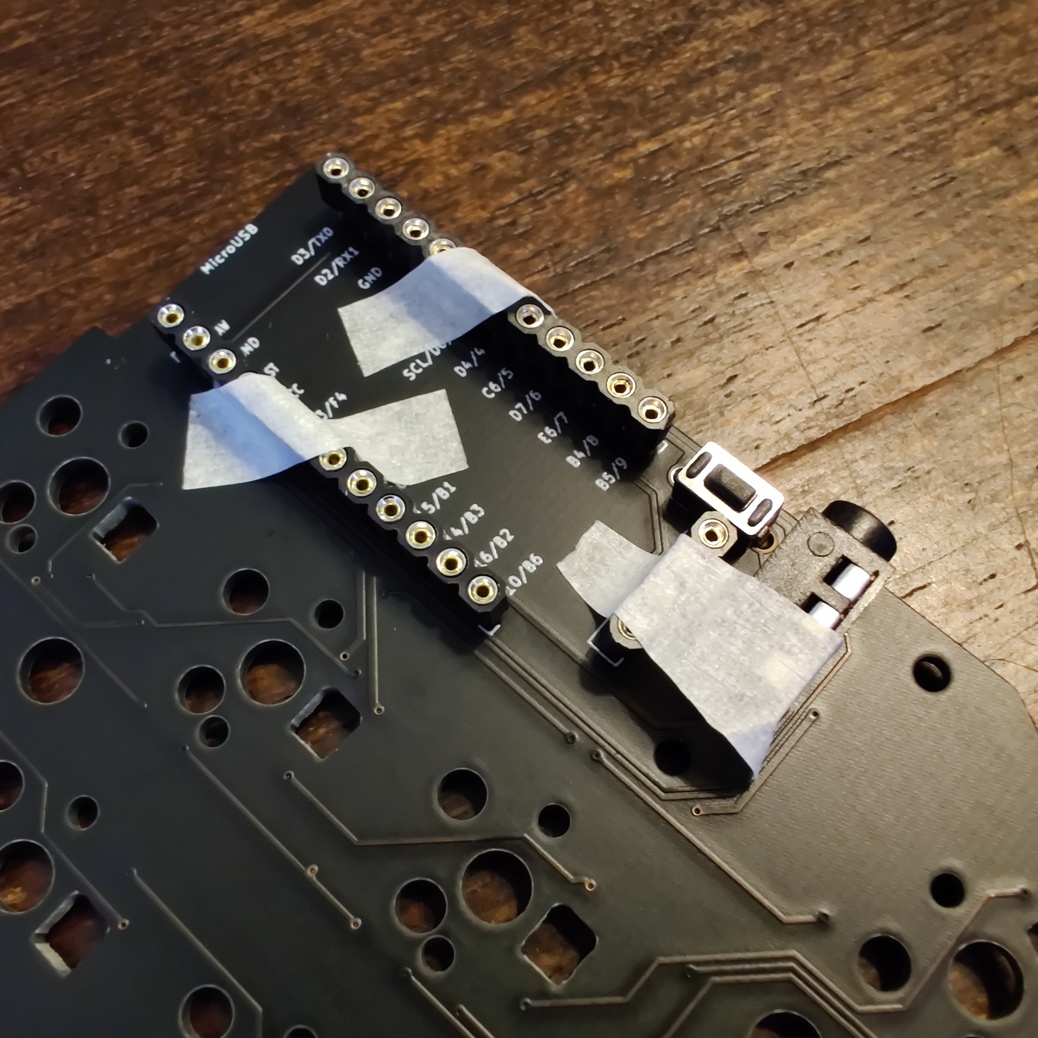
I used some masking tape to help me organize the wires.
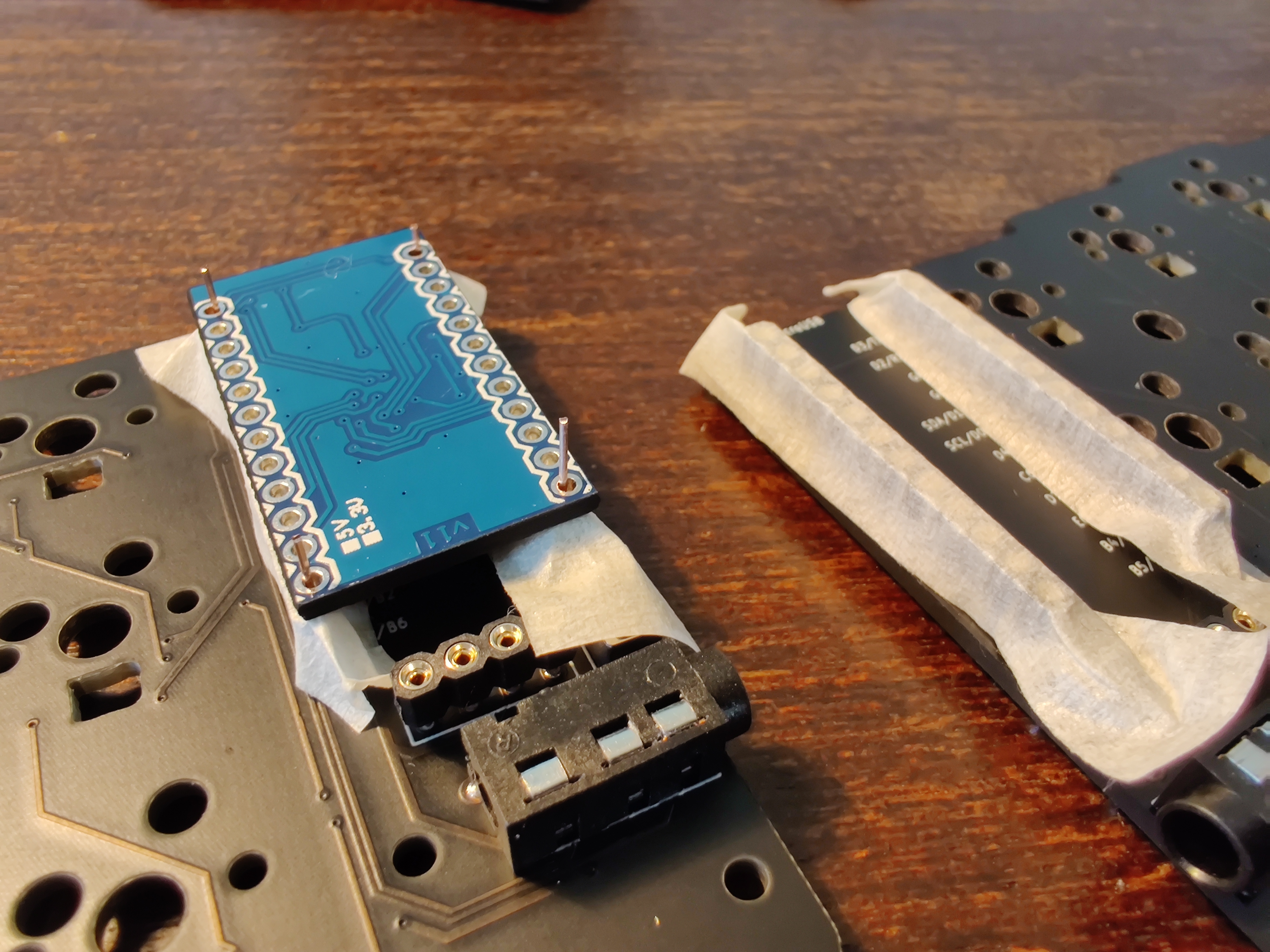
Also another benefit of using masking tape is to don't let the solder go thought the hole and "glue" with the PCB socket.
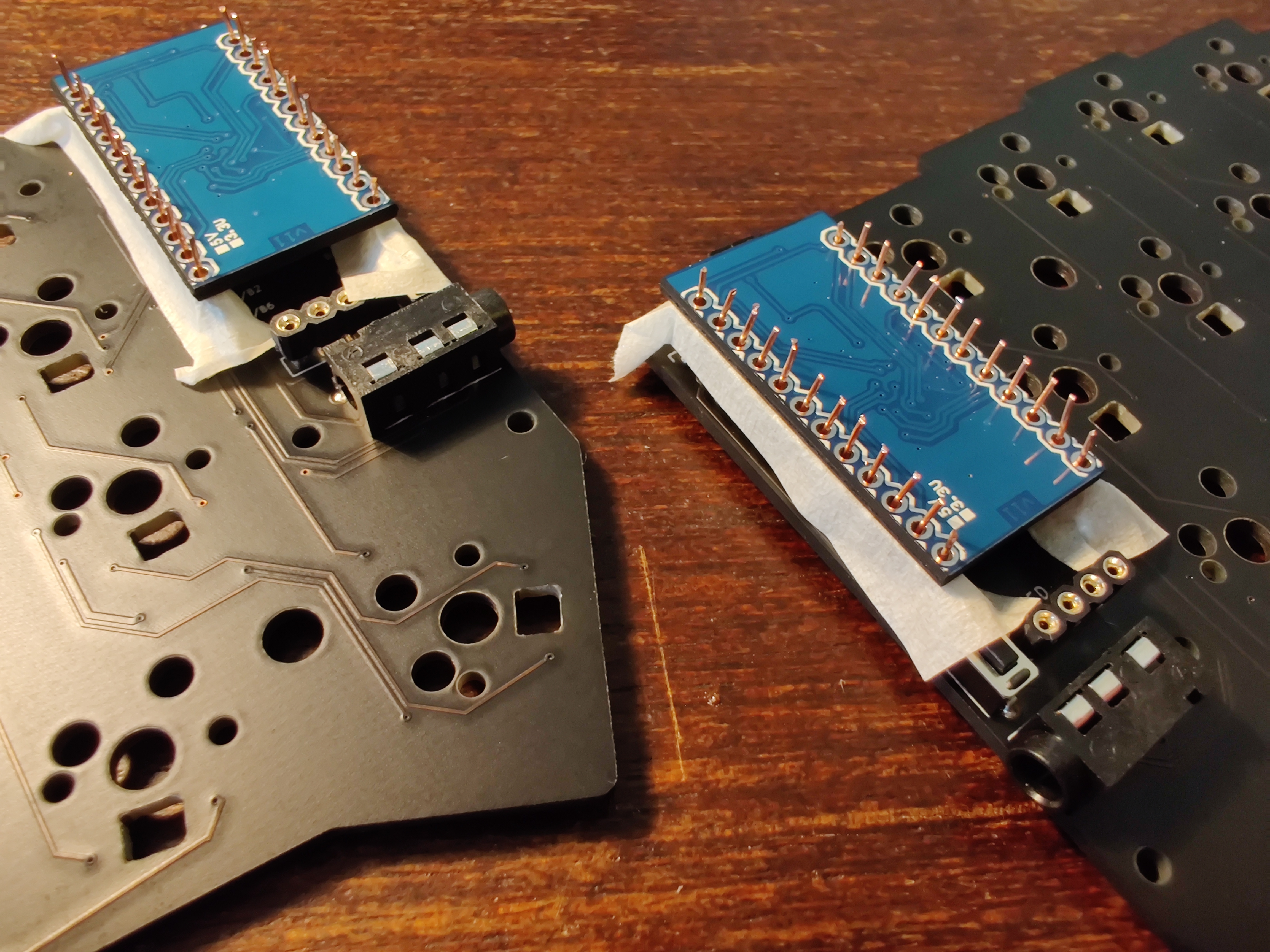
I used isolation tape to separate the led from the pro-micro
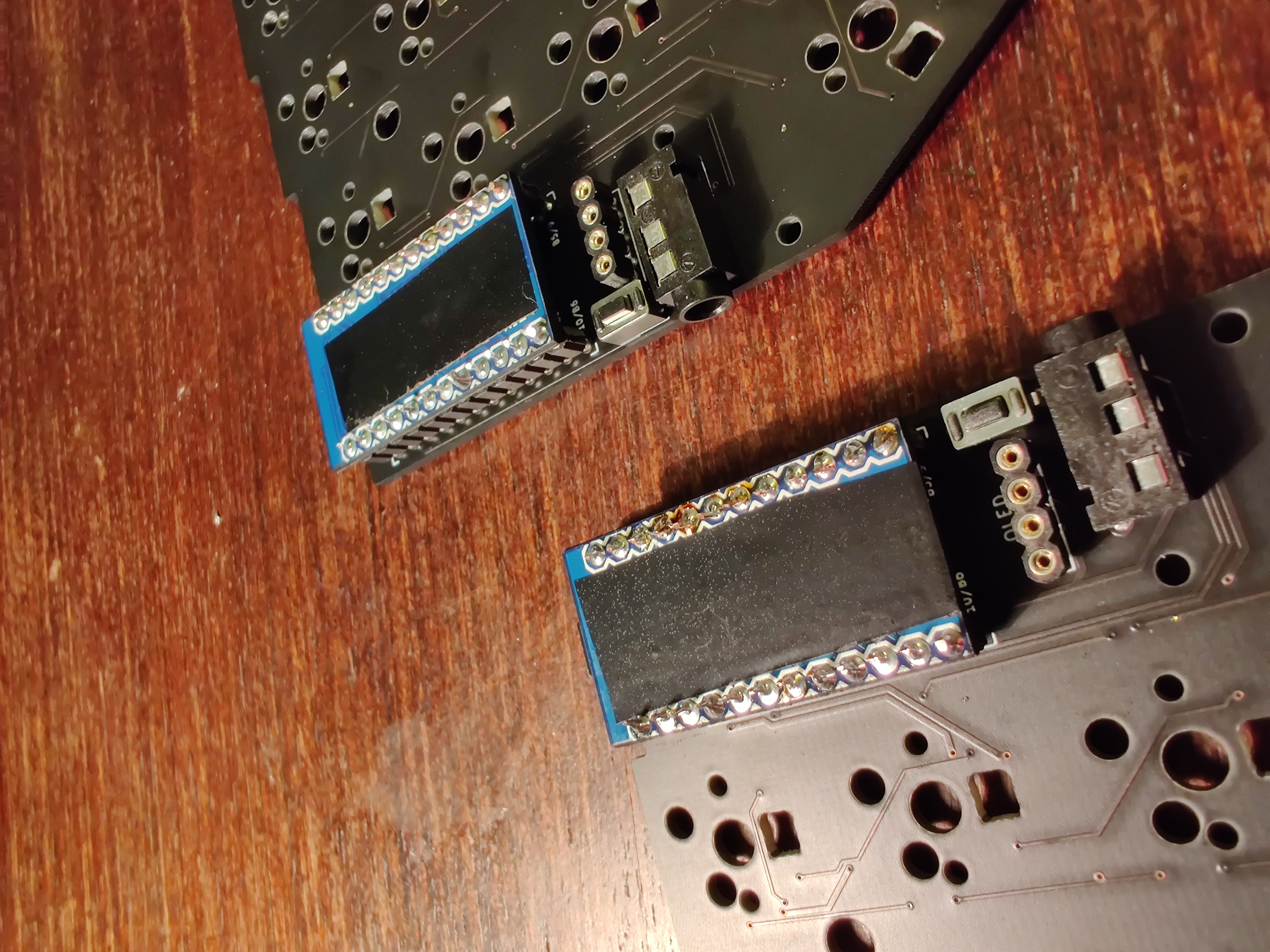
Same process as the pro-micro.
The SMD diodes are trick at first, they are pretty small and they have polarity, make sure to match the polarity with PCB.
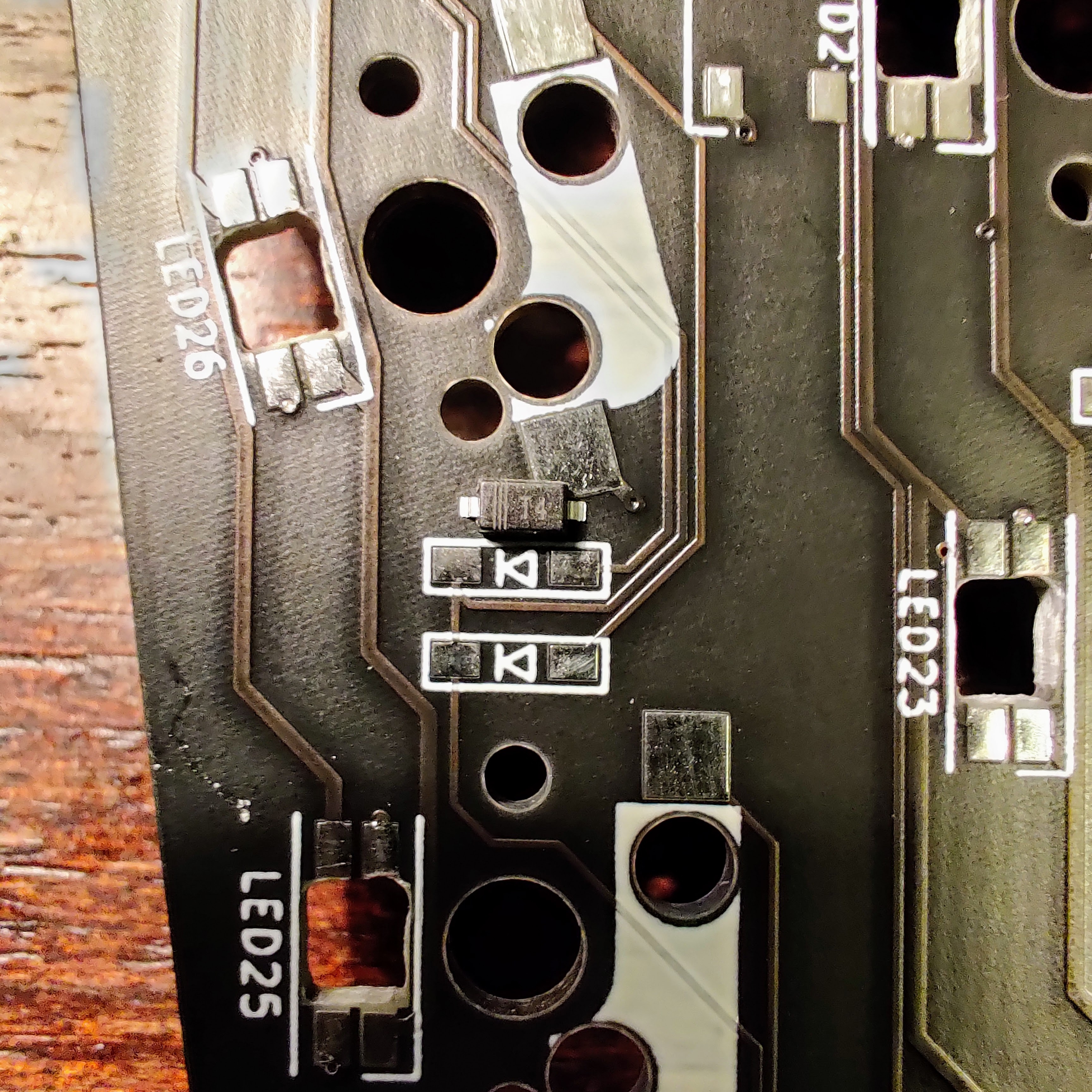
To make it easier to solder, first put some solder on one of the PCB diode contacts and then with a tweezer hold the diode over the solder and heat it to stick the diode, proceed to the other diode contact and solder it normally.
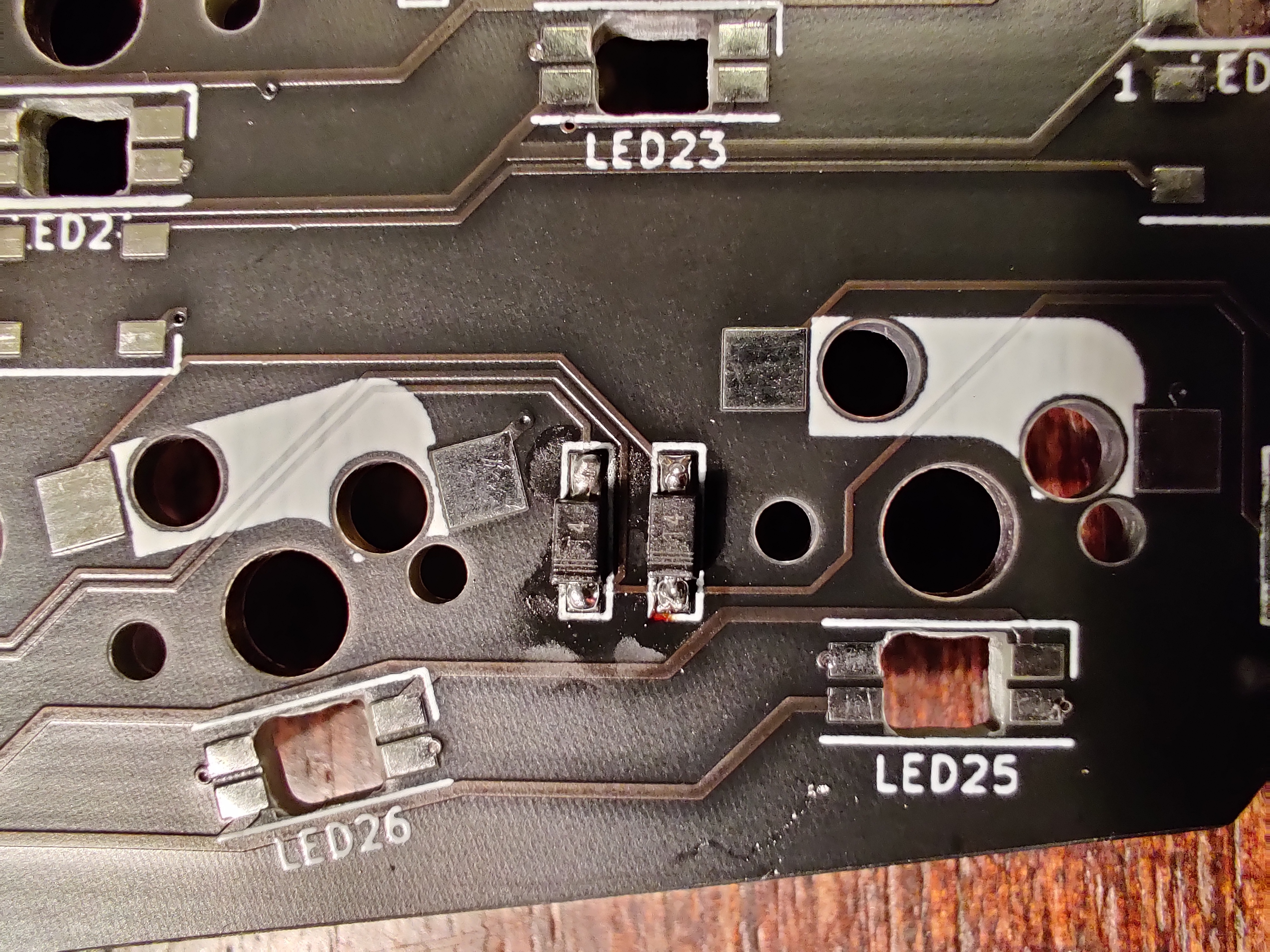
Very similar to soldering the diodes, but with a way bigger component.
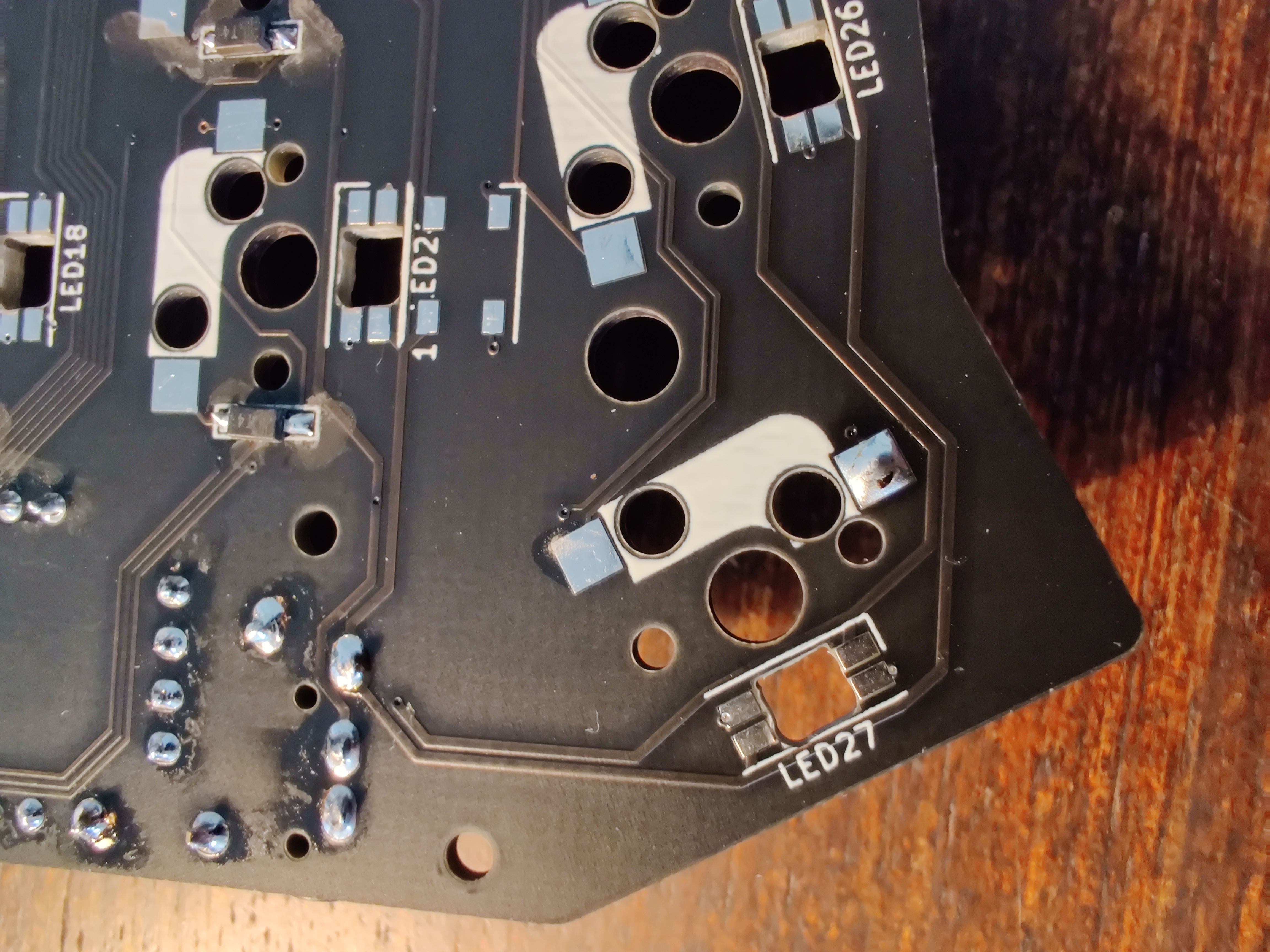
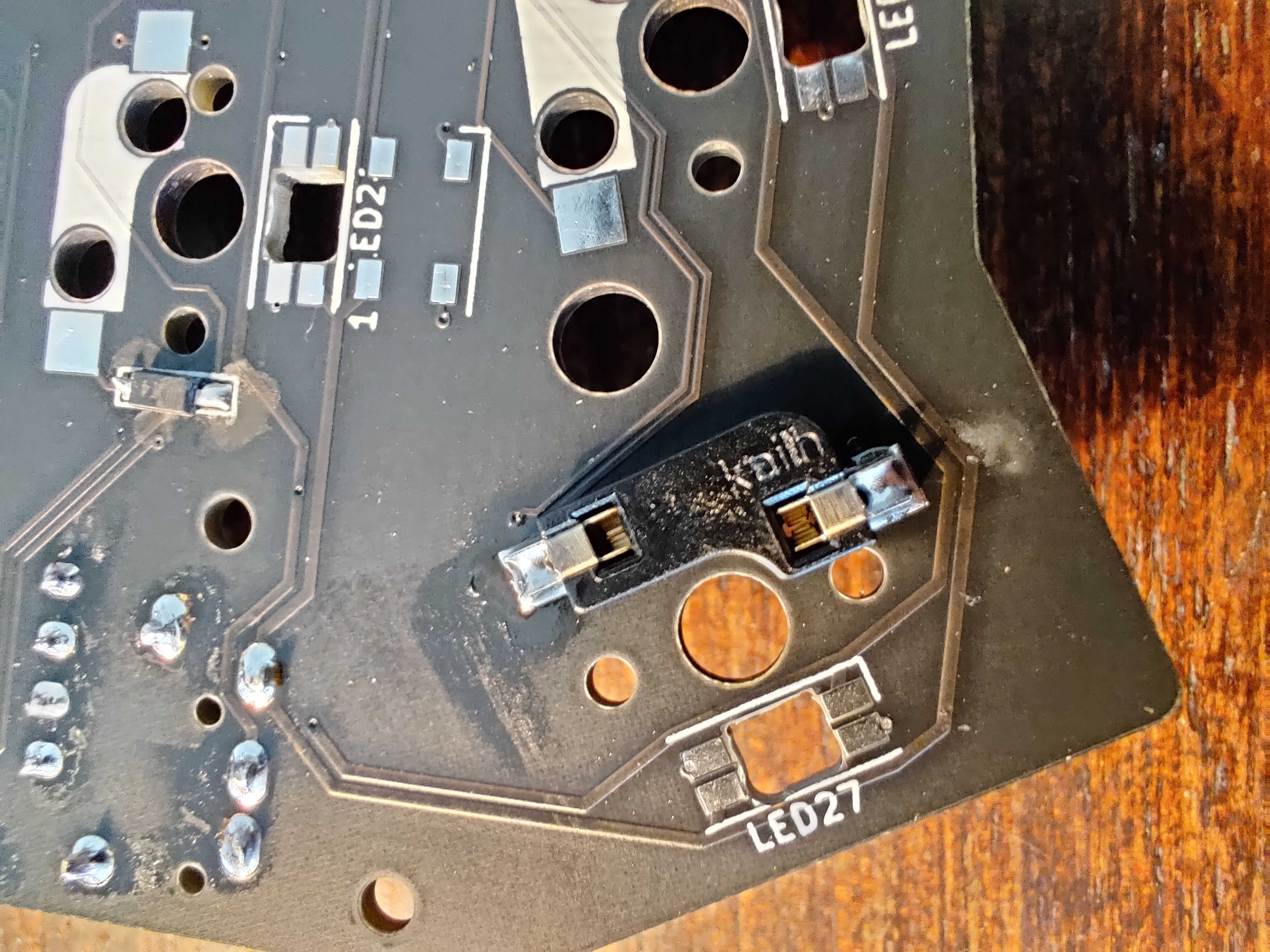
All leds have polarity make sure you align your as picured bellow.
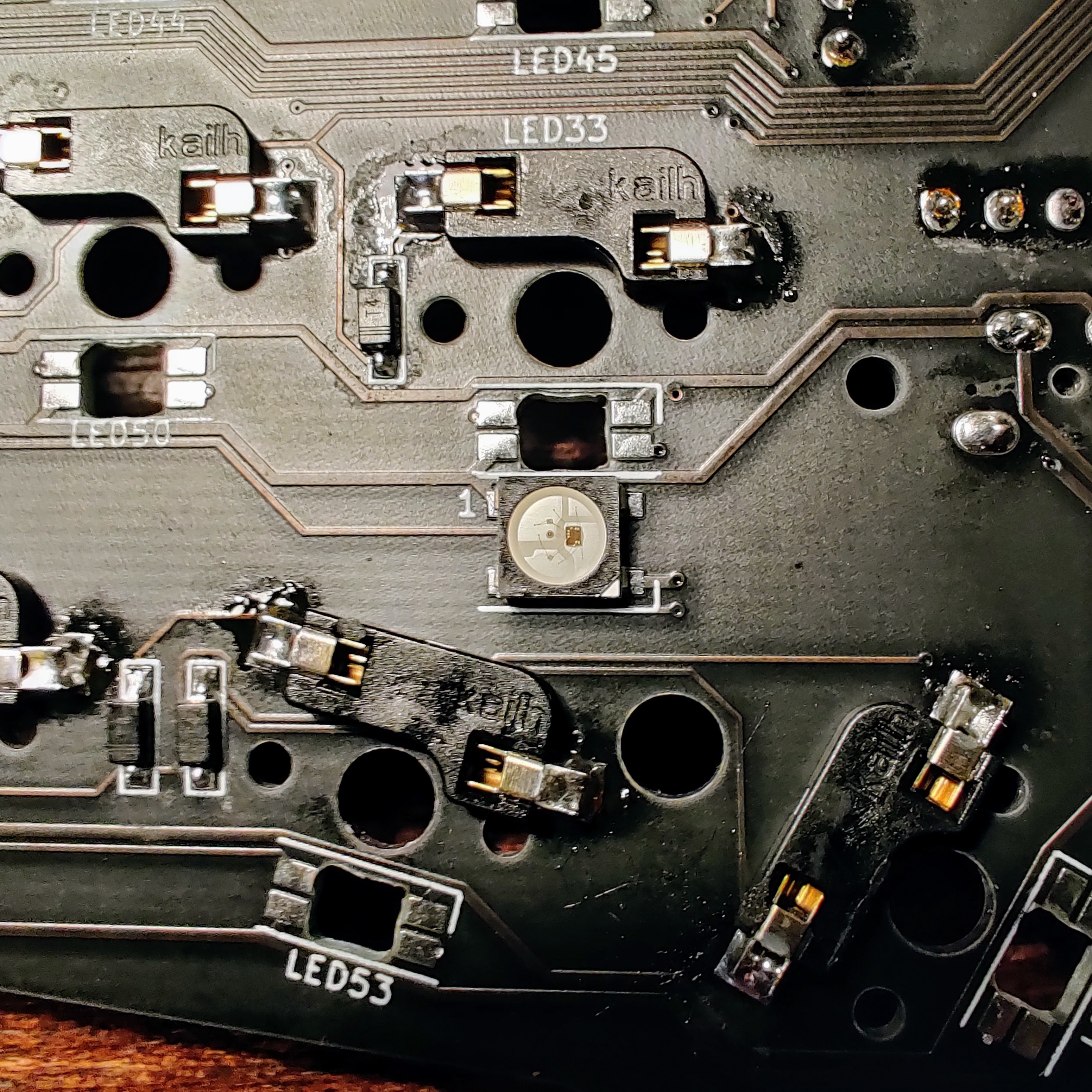
As the diodes, first put some solder on one of the PCB led's contacts and then with a tweezer hold the led over the solder and heat it to stick on the pcb, proceed to the other leds contacts and solder it normally.
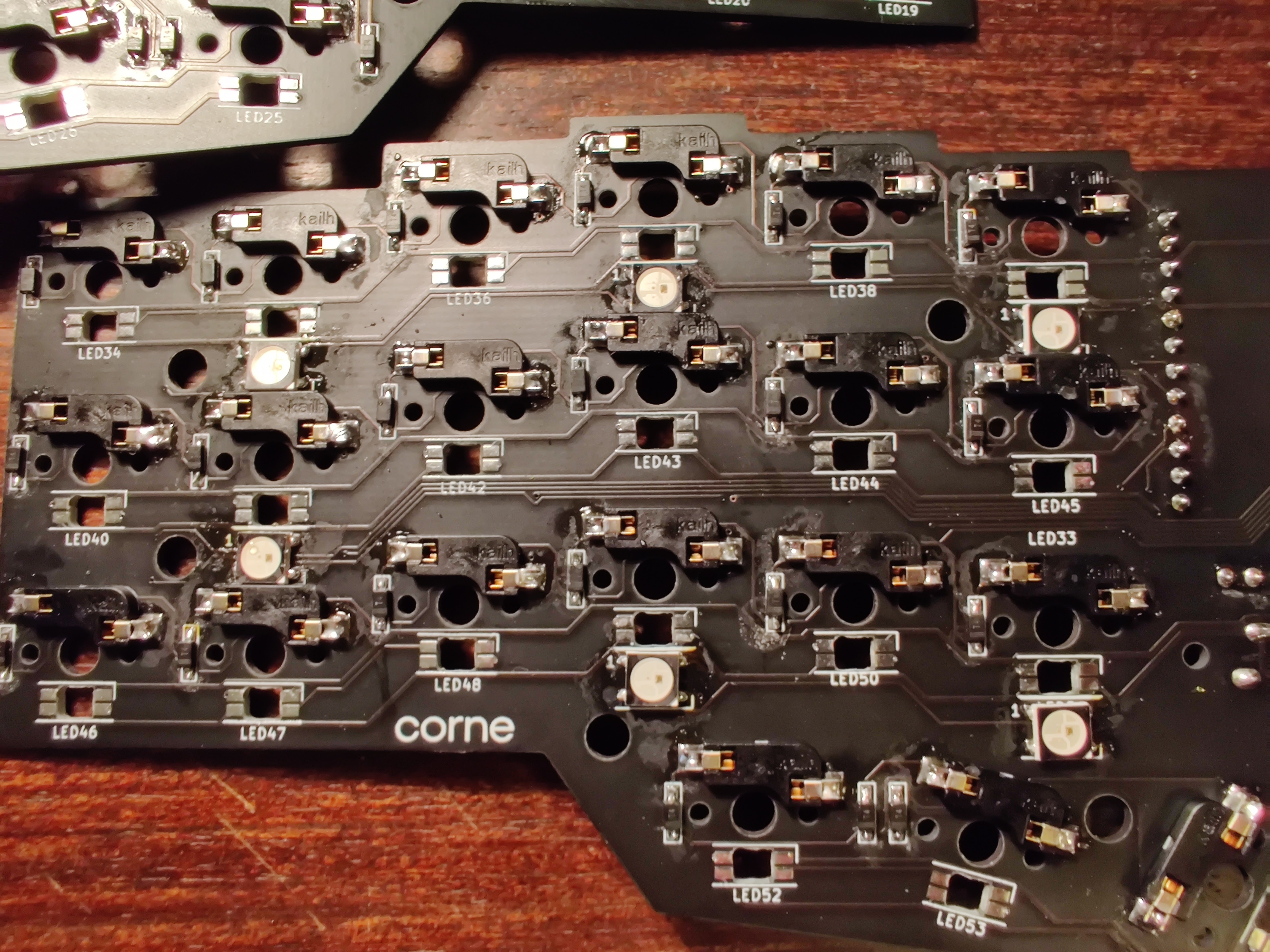
This led is quite challenging to do, be prepared fo some arduous solder job, make sure you have some flux to guide your lead.
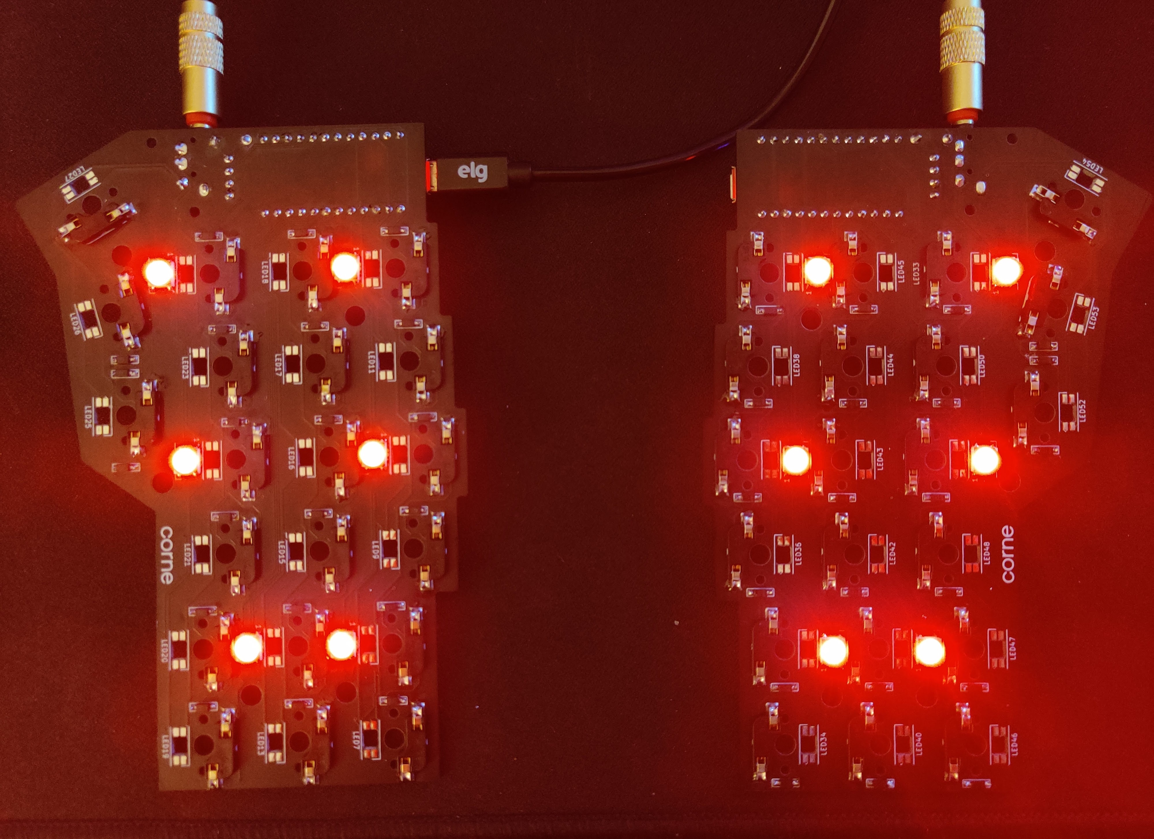
Exacly as the other leds, this leds also have polarity align as picured bellow.
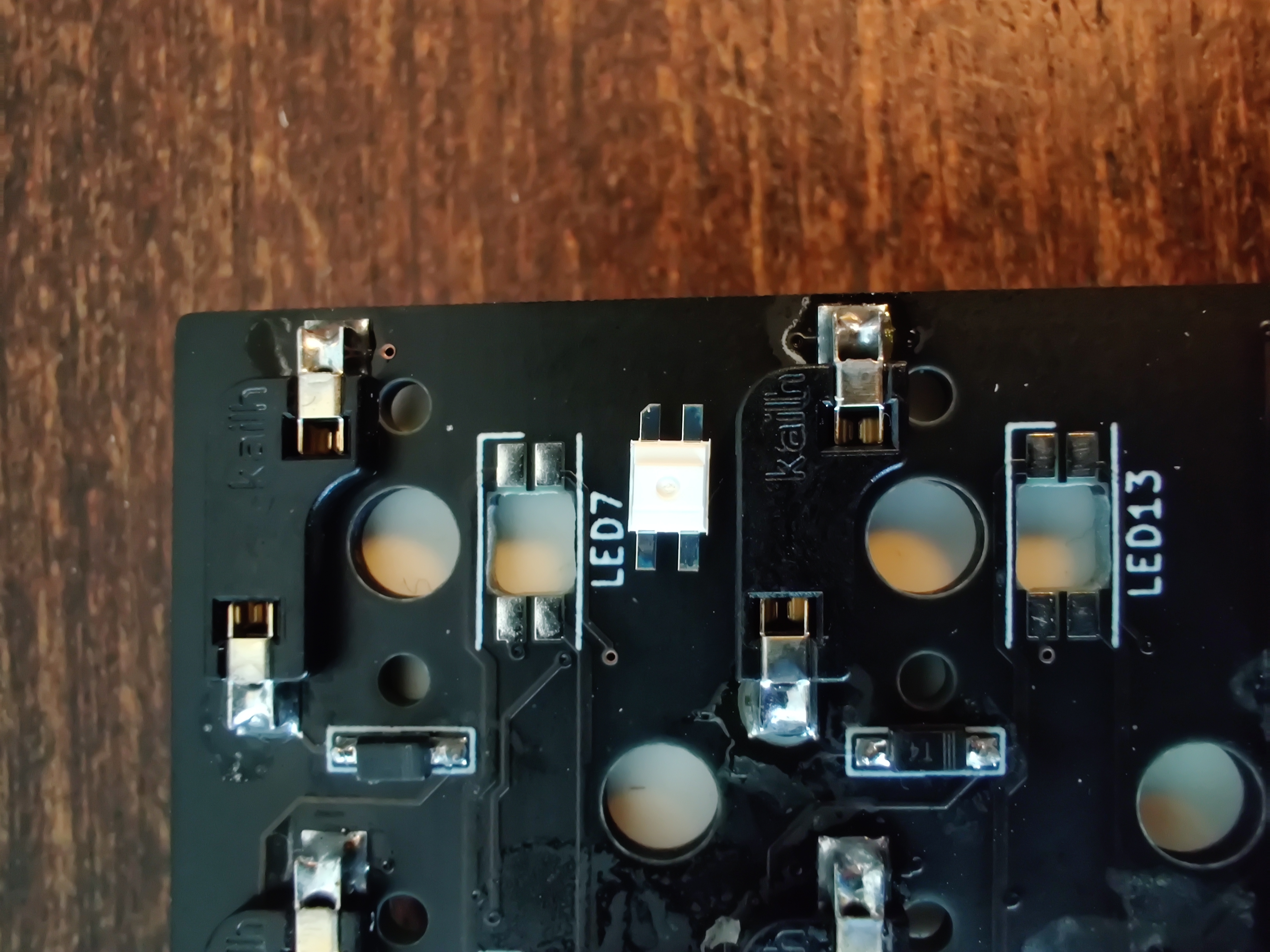
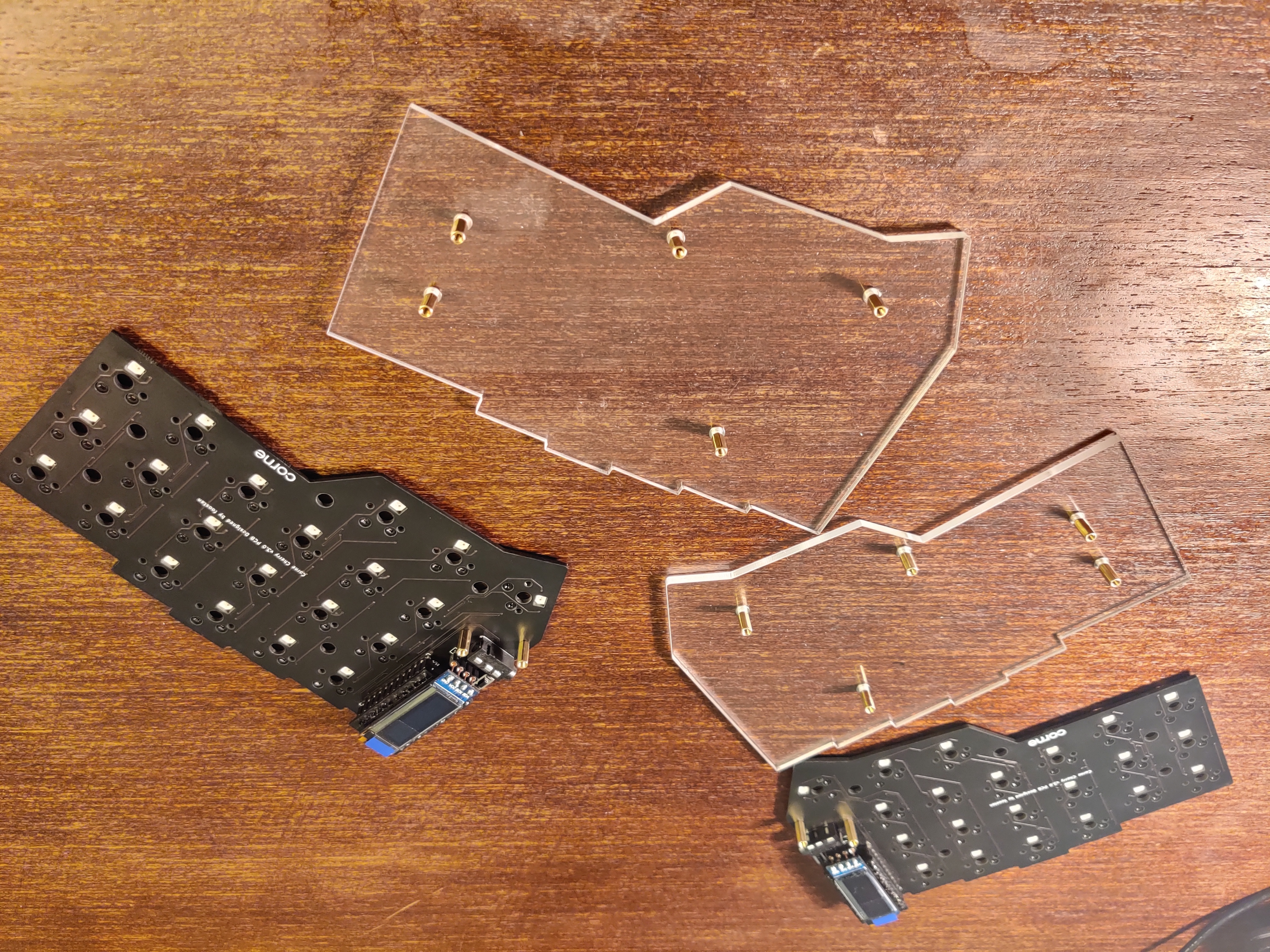
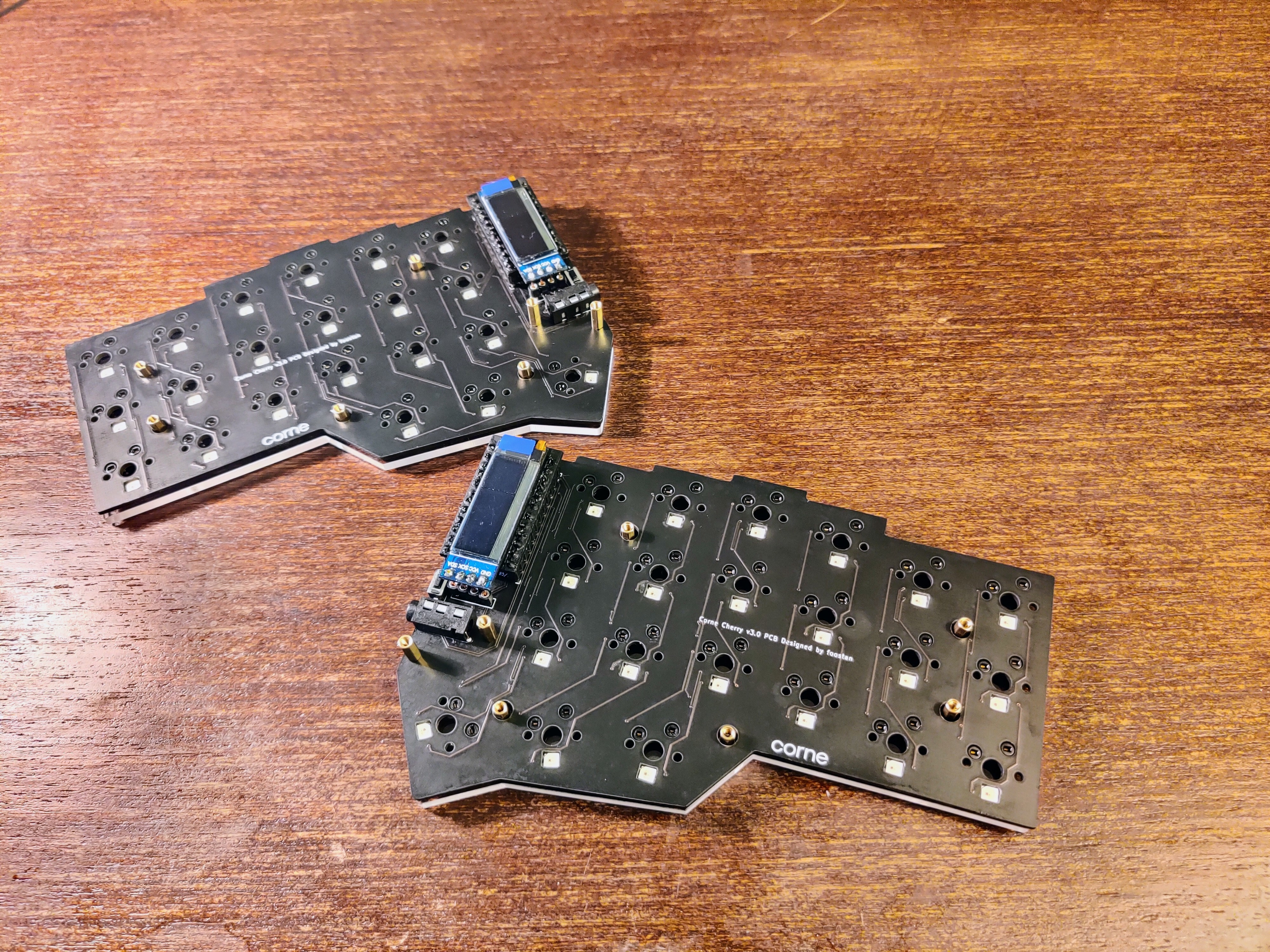
Just some screws and the build was almost finished.
