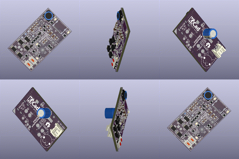
Ever wanted to charge your phone of your bikes dynamo? This Project does just that, for cheap (ish).
The incoming AC voltage from the dynamo gets rectified by 4 shottky-diodes and buffered in a high-capacity capacitor. Once a sufficient driving speed is reached and the capacitor is charged enough, the ATtiny1616 MCU on the board wakes up.
It measures the frequency of incoming AC voltage, which is corrolated to the driving speed, until it reaches the first threshold. Once the first threshold is reached, it can be assumed that enough power is available to charge the phone at 2.5W. The MCU enables the high efficiency DC/DC-Converter IC to generate 5V at the USB Type C Port. The pull-ups in the FUSB302 IC are set to signal to the attached device that 2.5W (500mA) are available. This prevents constant starting and stopping of the charging process, which is annoying. If the frequency is high enough to reach the 5W or 7.5W thresholds, 5W or 7.5W will be signaled via USB C power delivery.
If the device detects a DC source, it enters configuration mode. In configuration mode, the 2 buttons are used to select which threshold to calibrate. Connecting it back to a bike dynamo, it is now in calibration mode. The MCU will detect the needed speed to generate enough power for the prev. selected power level by connecting a 3W, 6W, or 9W constant power load and driving at a steadily increasing speed. Once the PowerGood signal does not drop out for 5 seconds with the load connected, a sufficient speed has been reached and is saved to EEPROM.


