Get all the parts / raw material:
- For the 3D printing there are two options:
- Filament, which is the basis for 3D printing. Luckily I could print at my work-place which reduced the cost from 210€ to 70€. The kind of filament you need depends on the 3D printer you have available.
- Buy the printout of adareth’s model at shapeways for 210€ over here http://www.shapeways.com/designer/adereth/creations
- Decide on the switches
- If you are going to invest a whole lot of time and money for a custom keyboard instead of buying one for 10€ I’d recommend to use your favorite switch-type. To make a well-informed decision I bought a switch-tester for this from massdrop and decided on Cherry MX Whites. https://www.massdrop.com/buy/varmilo-switch-tester-with-anodized-case
- I ordered 70 Cherry MX Whites from here: https://mechanicalkeyboards.com/shop/index.php?l=product_detail&p=847
- Decide on the key caps
- On the glamour shot you can see the 1976 keycap set; it used to be sold over here: http://pimpmykeyboard.com/sa-1976-keycap-set/ but the link is dead right now. You could try this link: https://www.massdrop.com/buy/nineteenseventysix-sa-keycap-set but it is a massdrop which is way different from usual online-stores. If you find a site that sells these, make sure you get the right amount and type of keys according to the layout.
- I got the “TKL Base Set + TKL Modifier” from over here: http://pimpmykeyboard.com/dsa-pbt-abs-blank-keycap-sets/ but I’m still two long keys short, I will have to order those specifically and I have a bunch of keys I don’t use left-over.
- The USB-Cable that connects the keyboard to your computer
- It’s an USB 2.0 to USB Mini-B cable, make sure you get one that is 2 meters long, it really makes handling the keyboard so much more comfortable
- https://www.amazon.de/gp/product/B00NH11N5A/
- The main controller (right half)
- A Teensy 2.0, I got that one from here: https://www.pjrc.com/store/teensy.html
- The chip, connectors and cable to give life to the left half
- TRRS cable and jacks
- Got my TRRS cable from here: http://www.digikey.de/product-search/de?keywords=839-1257-ND
- Got my TRRS jacks from here: http://www.digikey.de/product-search/de?keywords=CP-43514-ND
- MCP23018 16 bit IO Expander
- Got mine from here: http://www.digikey.de/product-search/de?keywords=MCP23018-E%2FSP-ND
- TRRS cable and jacks
What I spend on my keyboard (should give you a rough estimate for your build):
| item | cost |
|---|---|
| filament | 70 |
| switch-tester | 30 |
| key-caps | 70 |
| teensy 2.0 | 30 |
| switches | 60 |
| usb cable | 10 |
| IO Expander, TRRS jacks and cable | 30 |
| overall cost | 300 |
My choices / advantages:
- Using the soldering iron at the uni-workshop for free
- 76 Diodes for free
- Soldering wire and copper for free
- All the resistors used for free (5 resistors are used)
- Several files for working out the rough edges of the 3D-printout
Depending on what you have available you might spend more or less money than me; however, 300€ is a good rough estimate.
After all the parts have arrived it is safe to move on to the next section.
It is assumed that you have printed the casing successfully.
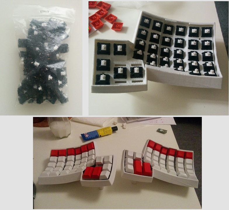
- Plug the switches into the casing. No glue is needed; the casing provides the perfect fit.
- Put the keycaps on the switches
- Note that in the pictures here some of the long keys on the thumb-part are too short; that’s why it doesn’t look symmetrical
Now going further on in the guide there are two options
- The first option is to print flexible PCBs. The advantage is that you save a lot of wiring
business, everything looks rather clean and you don’t have to worry about your cables being too
thick such that the casing doesn’t close. However, if you don’t have the means to print out such
PCBs there is the second option, wiring everything by hand.
- The guide for this PCB-option is very rough indeed and it doesn’t include the firmware
used. Wiring and firmware play extremely close together–wiring before knowing your
firmware is like buying a shoe without measuring your feet before. For this option,
information about the exact firmware is not published, this in addition to the fact that
the pictures in this rough guide are incomplete makes this option extremely
beginner-unfriendly. Going in blind-sided like this may lead to one of these things:
- reprogramming huge parts of the firmware to match your wiring, which comes with a ton of debugging.
- rewiring to adapt to what the firmware expects, which may easily double your work here.
- Route 1: Dactyl Flexible PCB Rough Guide
- The guide for this PCB-option is very rough indeed and it doesn’t include the firmware
used. Wiring and firmware play extremely close together–wiring before knowing your
firmware is like buying a shoe without measuring your feet before. For this option,
information about the exact firmware is not published, this in addition to the fact that
the pictures in this rough guide are incomplete makes this option extremely
beginner-unfriendly. Going in blind-sided like this may lead to one of these things:
- The second option is to hand-wire everything. For people like me, who had never soldered before,
this was great pain and pleasure.
- Here too firmware and wiring go hand in hand, you pretty much have to have a detailed look
at the firmware you are using before wiring anything. I provide my modification of the
“ergodox-firmware” over here: https://github.com/BubblesToTheLimit/ergodox-firmware
- TODO: Make a successfull pull-request, such that it is available in the official ergodox-firmware
- Some of the steps of this guide may not be described in much detail, but in contrast to option one there is a whole lot more information.
- Route 2: Dactyl Hand-Wiring Guide
- Here too firmware and wiring go hand in hand, you pretty much have to have a detailed look
at the firmware you are using before wiring anything. I provide my modification of the
“ergodox-firmware” over here: https://github.com/BubblesToTheLimit/ergodox-firmware
For now, take a look at the images and try to figure things out; I know that’s not great (it’s better than nothing!)
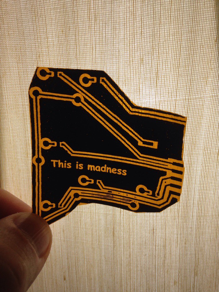
Get two sheets of 6in square Pyralux™. Use the Toner Transfer method to etch the Pyralux sheets as you would a usual PCB
NOTE: If you only have an Inkjet make photocopies of the print out. Voilà, Toner based copies!
Here’s a handy toner transfer guide …
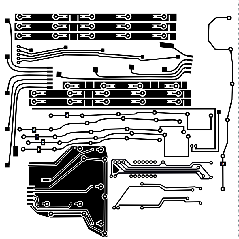
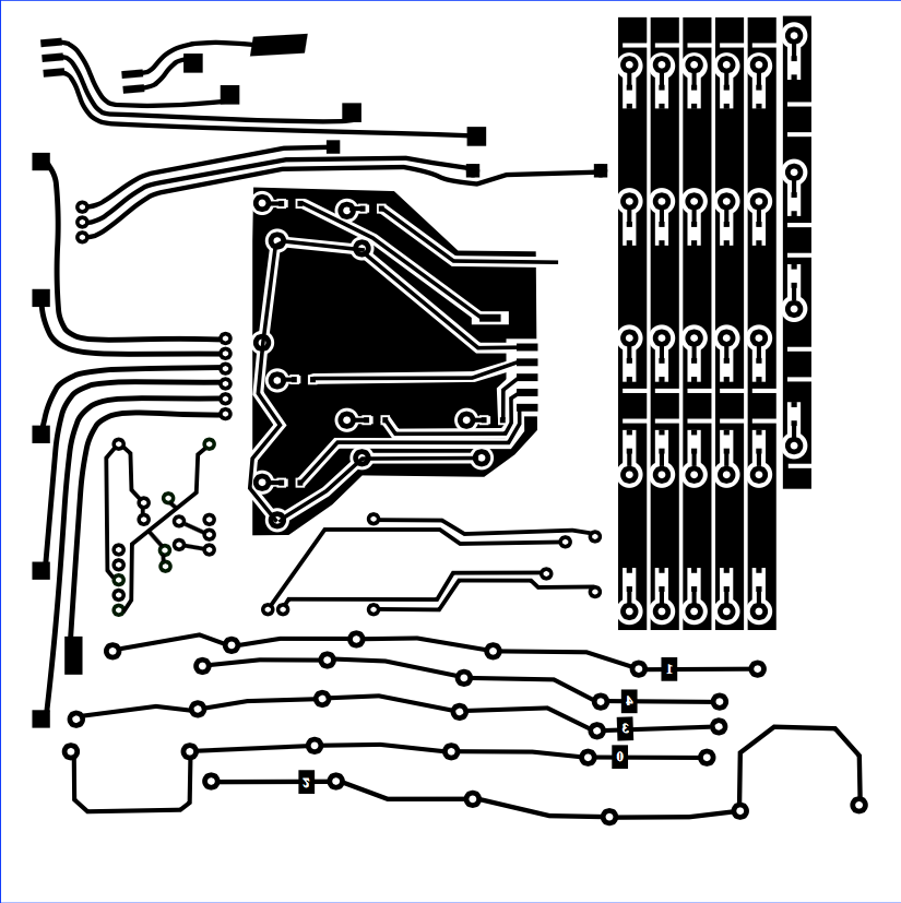
Print these PCB designs out…
Left hand:
Right hand:
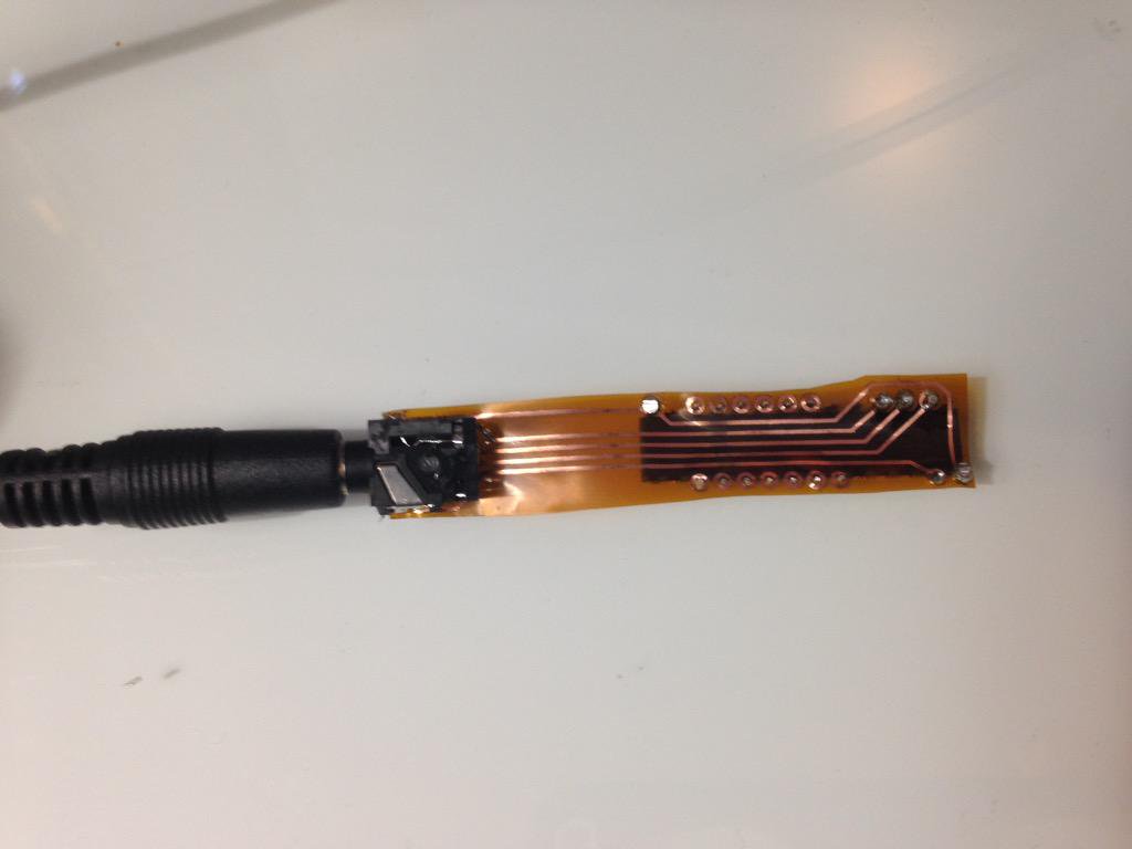
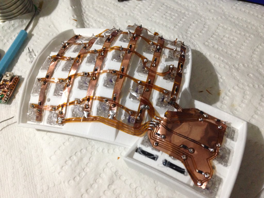
When you’re done etching, you’ll need to carefully cut the pcb into pieces… See the images below.
The thumb cluster pcb for the left hand:
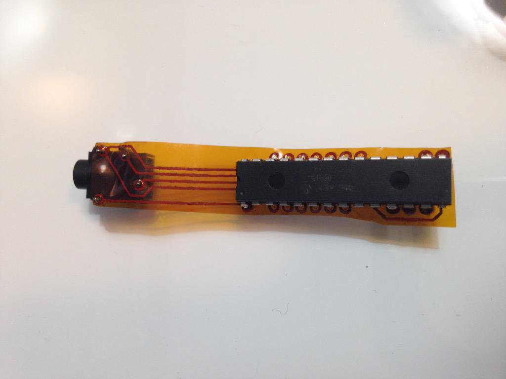
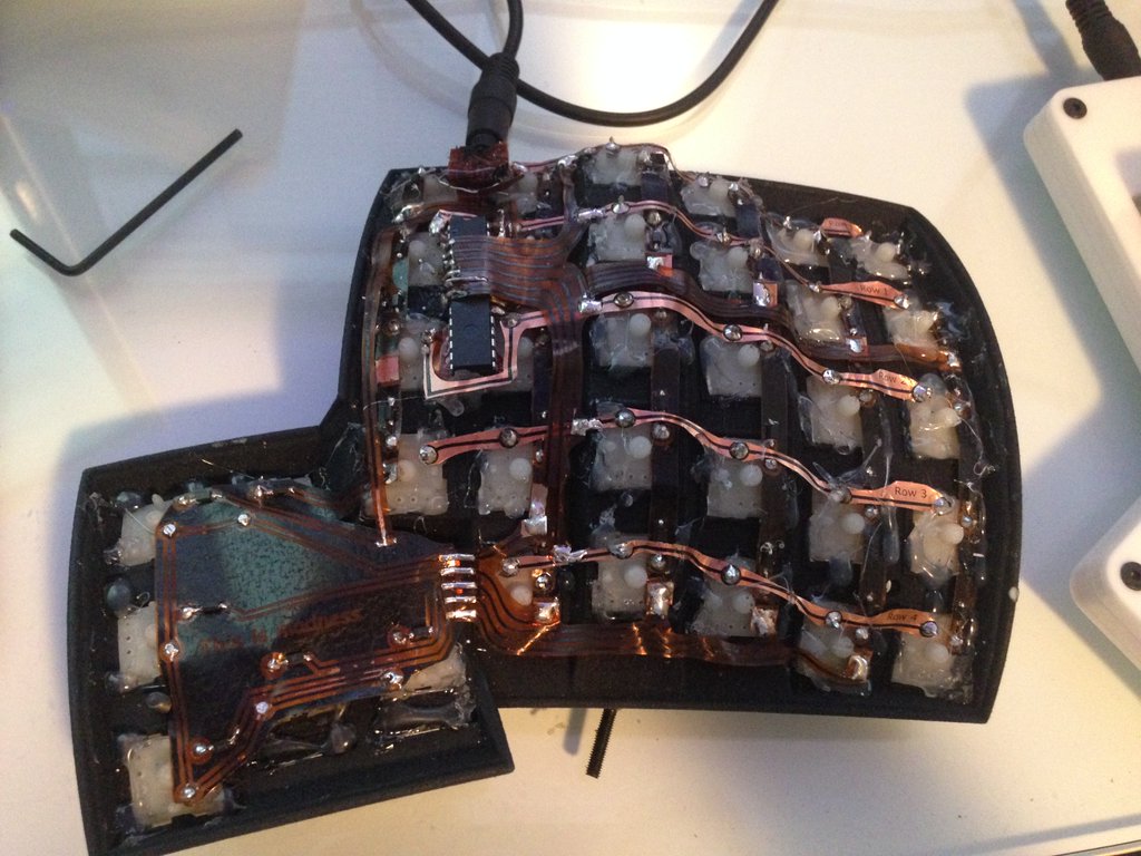
Solder the MCP like so:
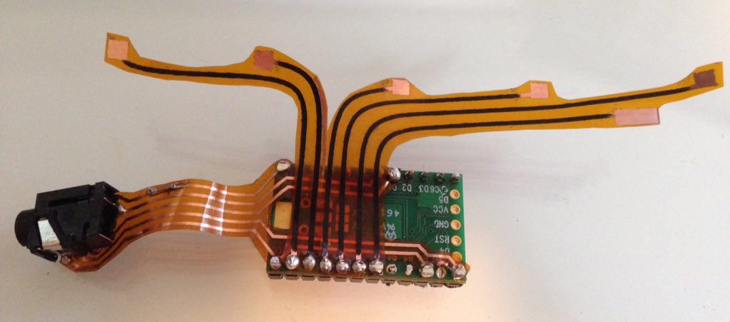
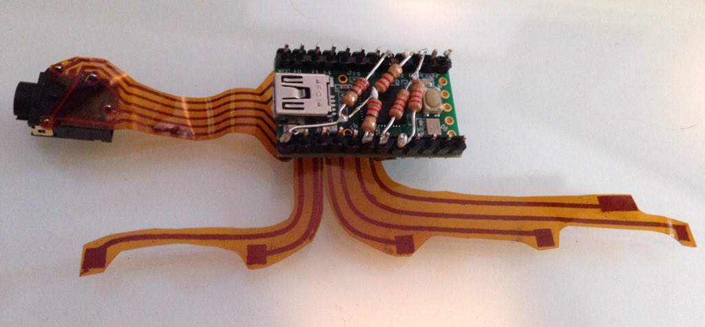
Solder the Teensy 2.0 like so:
The two 2.2kΩ (Red Red Red Gold) pull-up resistors ensure a clear signal between the USB controller and the I/O expander. Read more about pull-up resistors here.
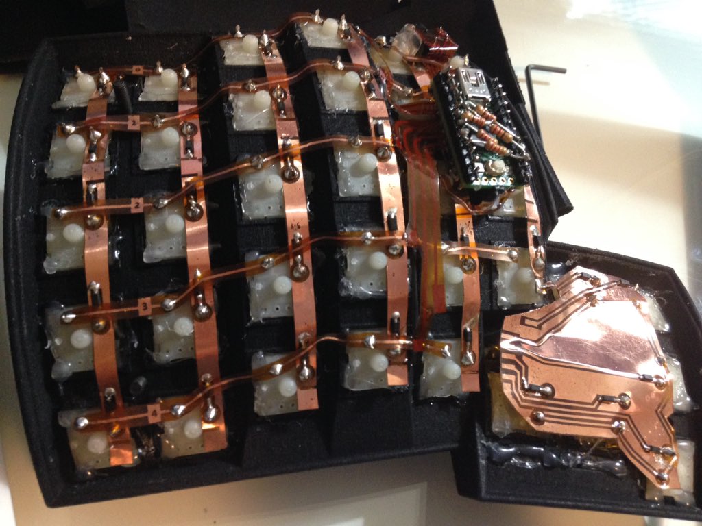
Each hand of the keyboard will wire up like so:
Teensy goes here… note the rows soldered to the teensy via the Pyralux:
Here the left hand:
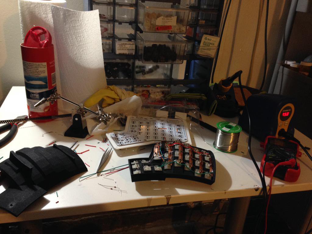
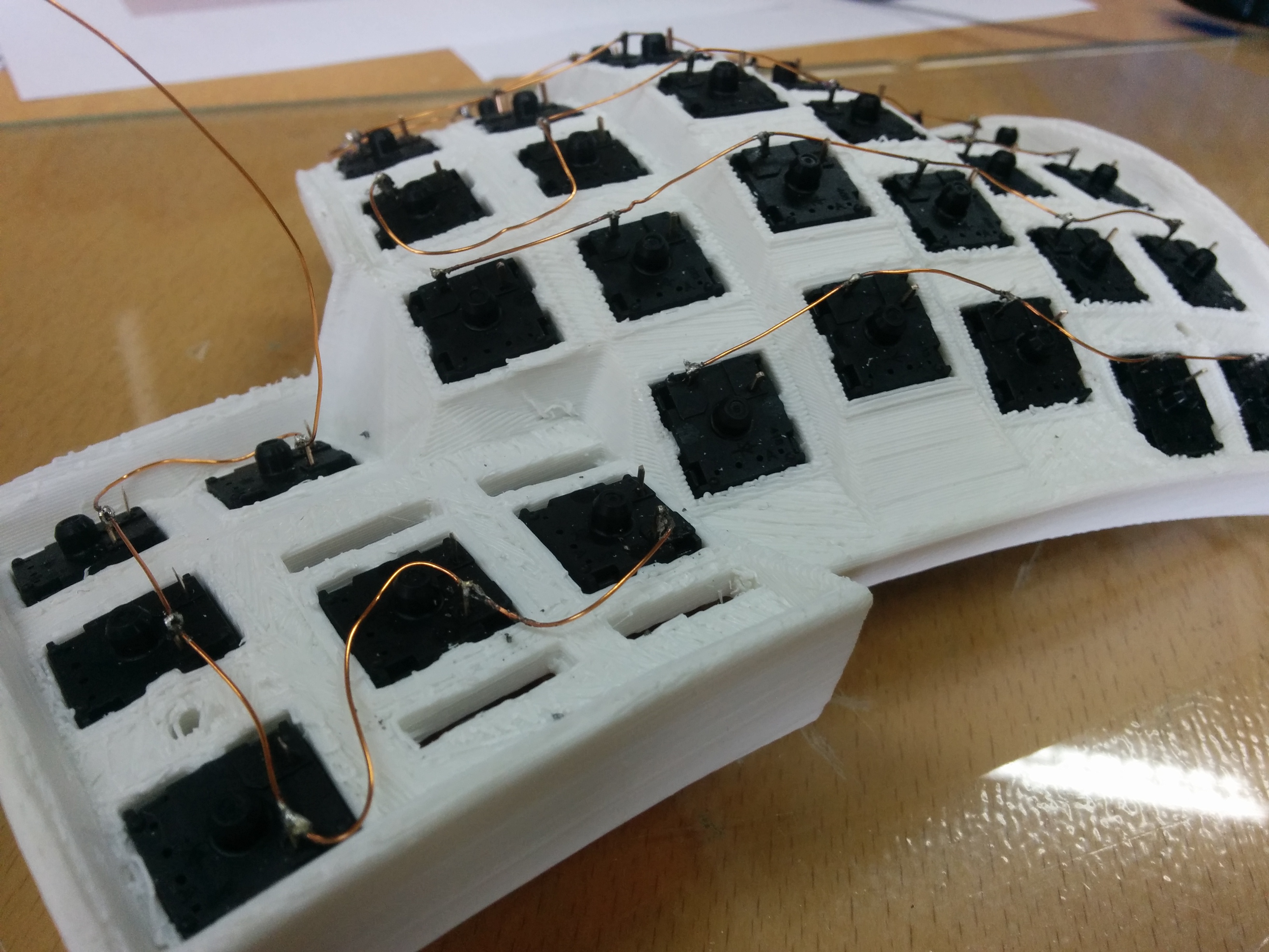
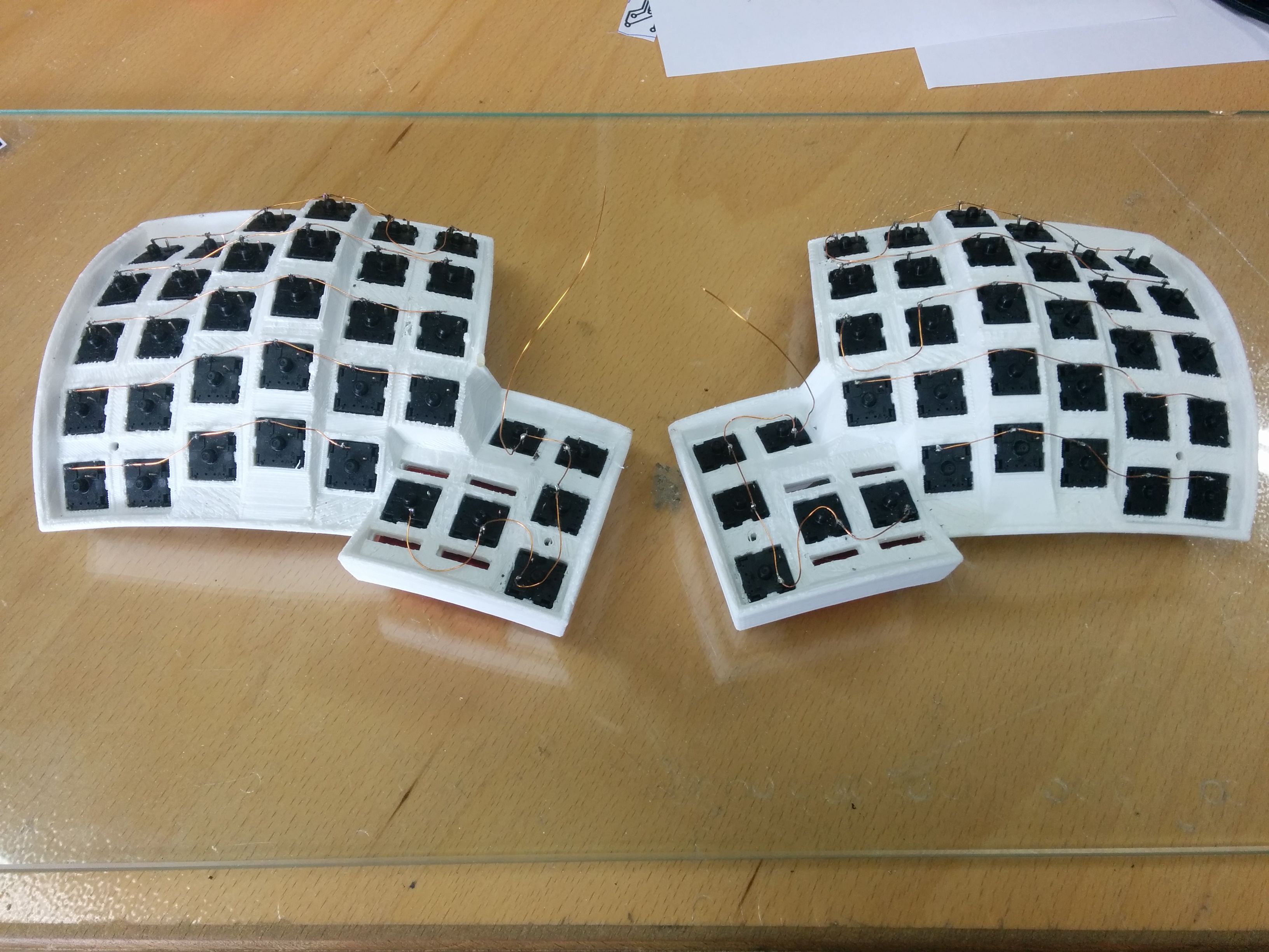
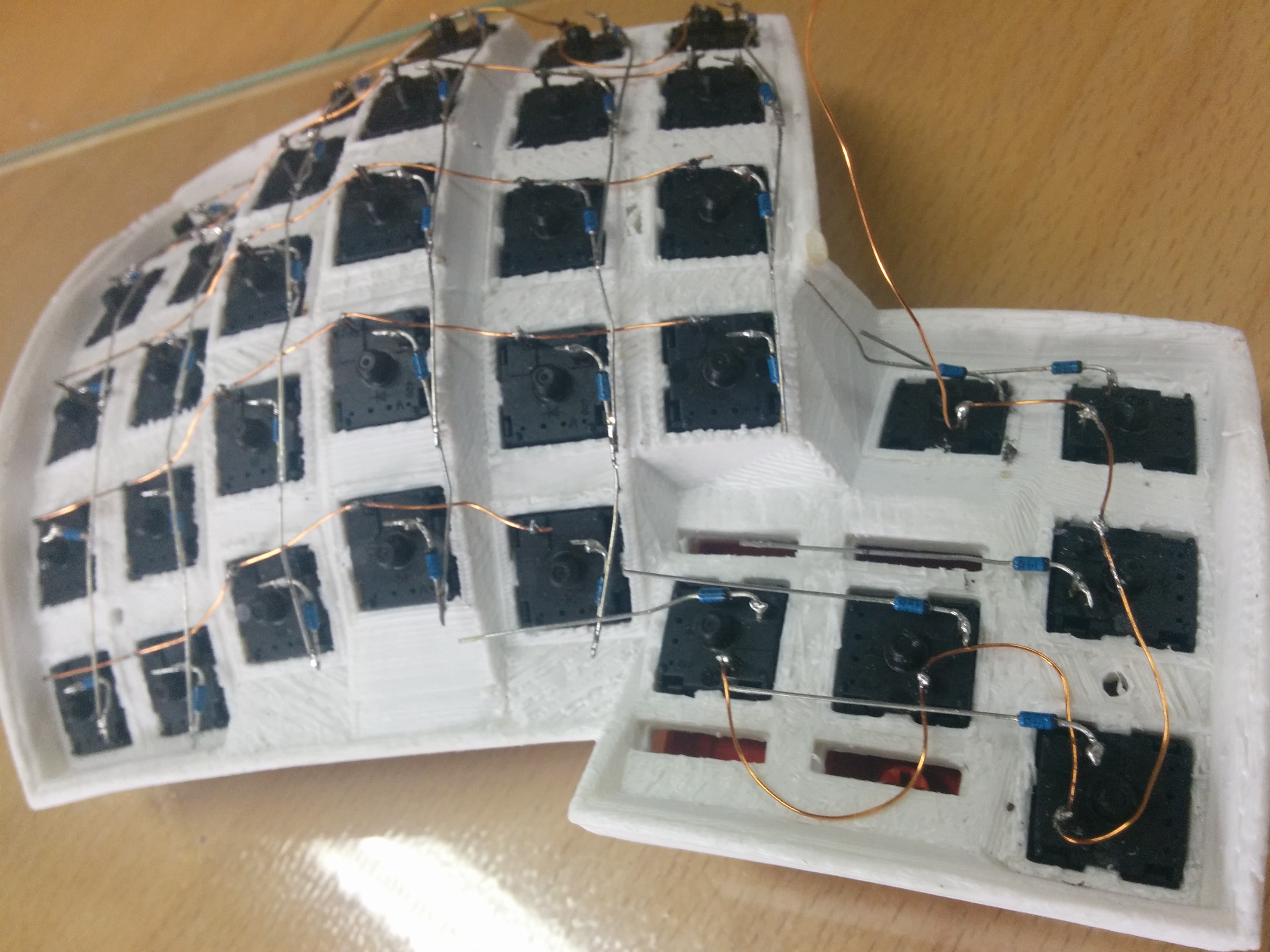
Using the copper wire you solder each row together, notice how the thumb-part gets its own row. If you take a close look you can see how I did do a messy job soldering, I had to redo some of the parts because they weren’t soldered properly. Do this for both sides. It doesn’t matter which of the two available pins of each switch you chose for the row, but for it to look clean you should decide for either one of them.
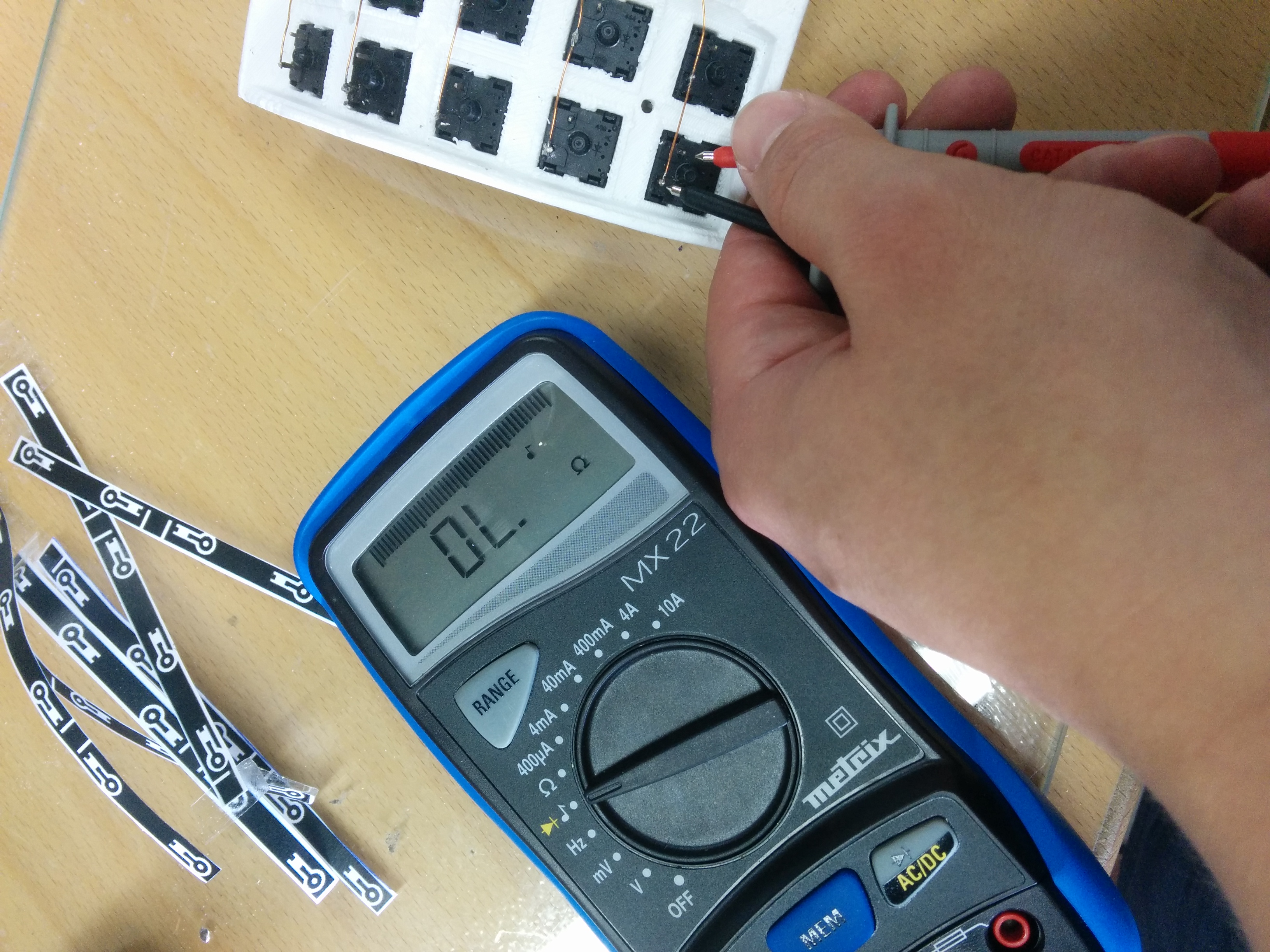
You might want to go ahead and test each one of the 70 switches with a multimeter.
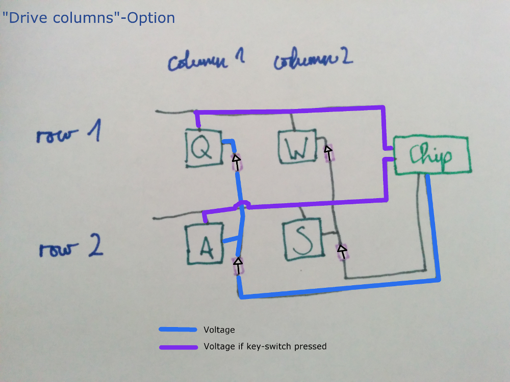
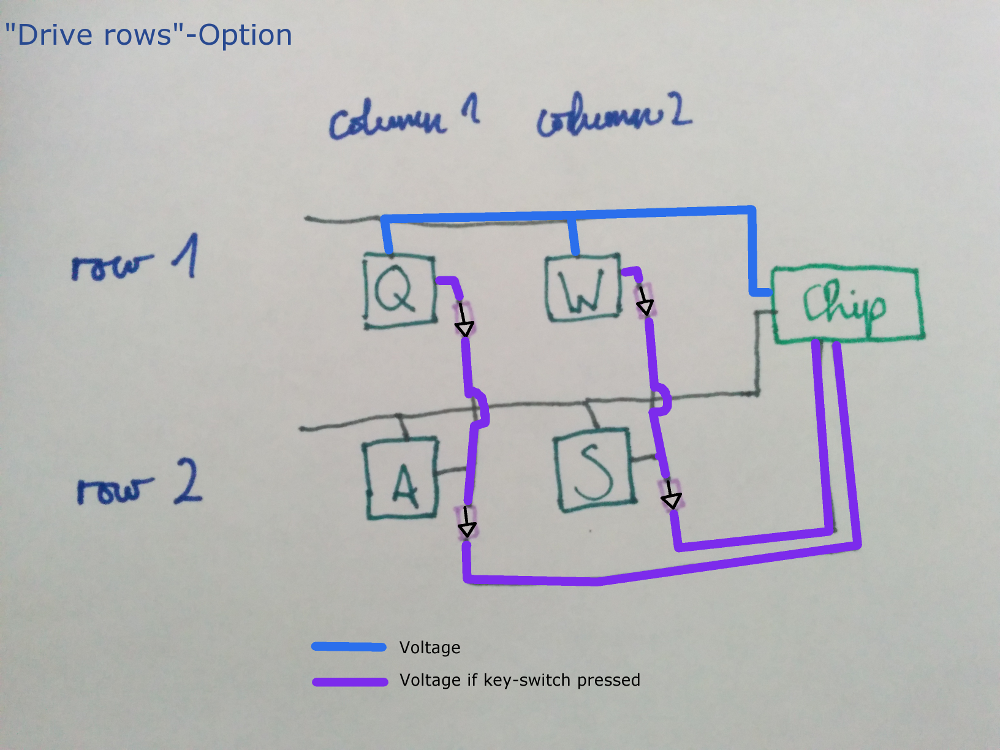
The next step is to create the columns by soldering the diodes. There are two options for soldering the diodes, all heading towards the switch or all heading away from the switch. These two ways are called “row-driven” or “column-driven” and here again it is cruciual for the firmware and the actual wiring to be on the same page.
If you want to try and use the “tmk_keyboard” firmware which seems to be also interesting you want to wire the diodes in the according way (check whether the tmk_keyboard firmware expects a row-driven or a column-driven setup).
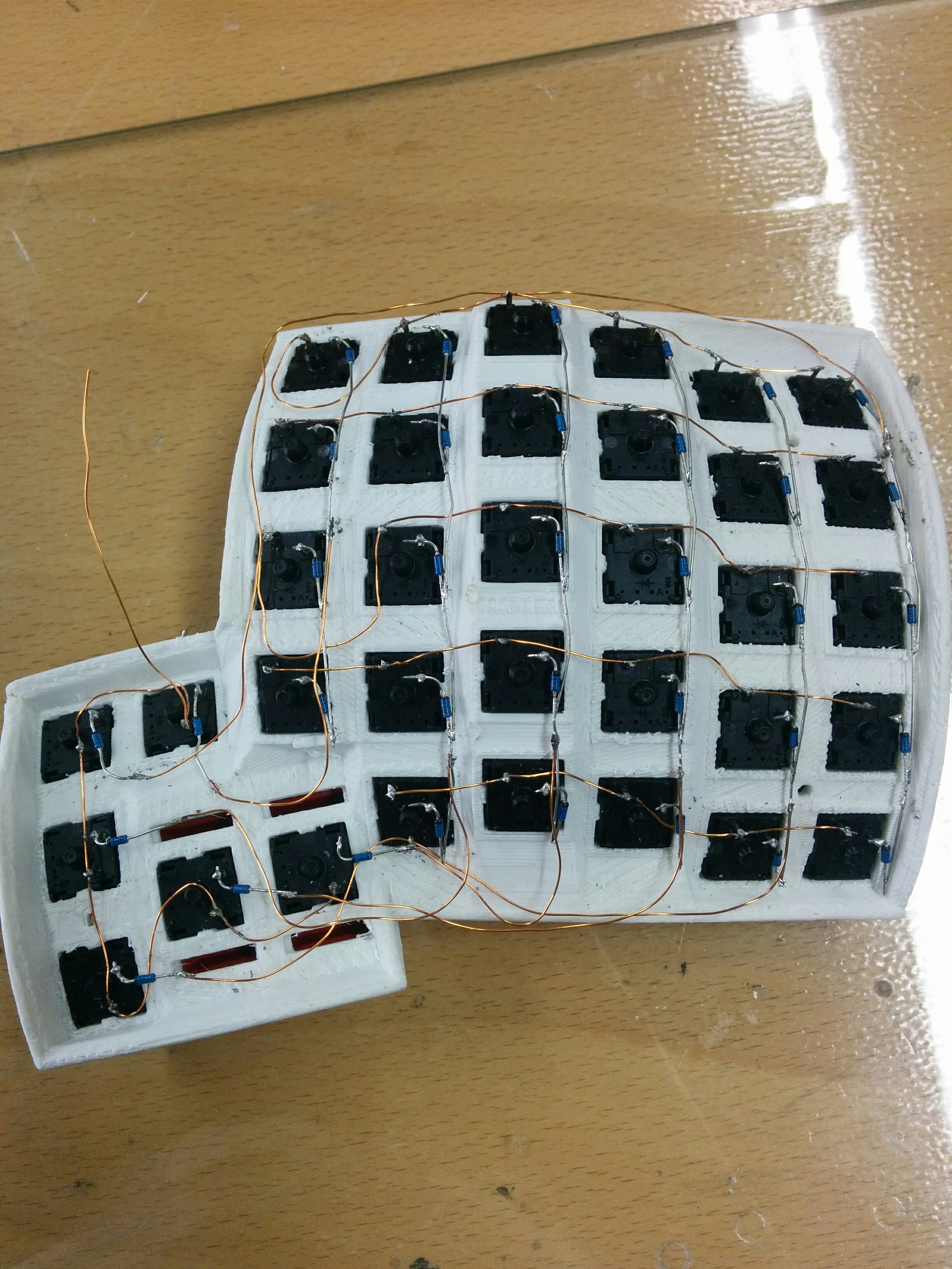
As you can see in these following pictures, I went for the “row-driven” setup (visible by the direction of the diodes, the black line being towards the key-switches). This first picture doesn’t show how the 6 thumb-keys are actually individually connected to the 6 main columns, but note the small black line on each diode.
This second picture shows how the 6 thumb-keys are actually connected to the 6 main columns.
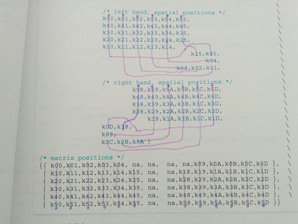
How thumb-keys are wired again depends on the firmware. The following picture shows the wiring of the thumb keys more clearly and also the part in the code that reflects this wiring (ergodox-firmware/src/keyboard/dactyl/matrix.h).
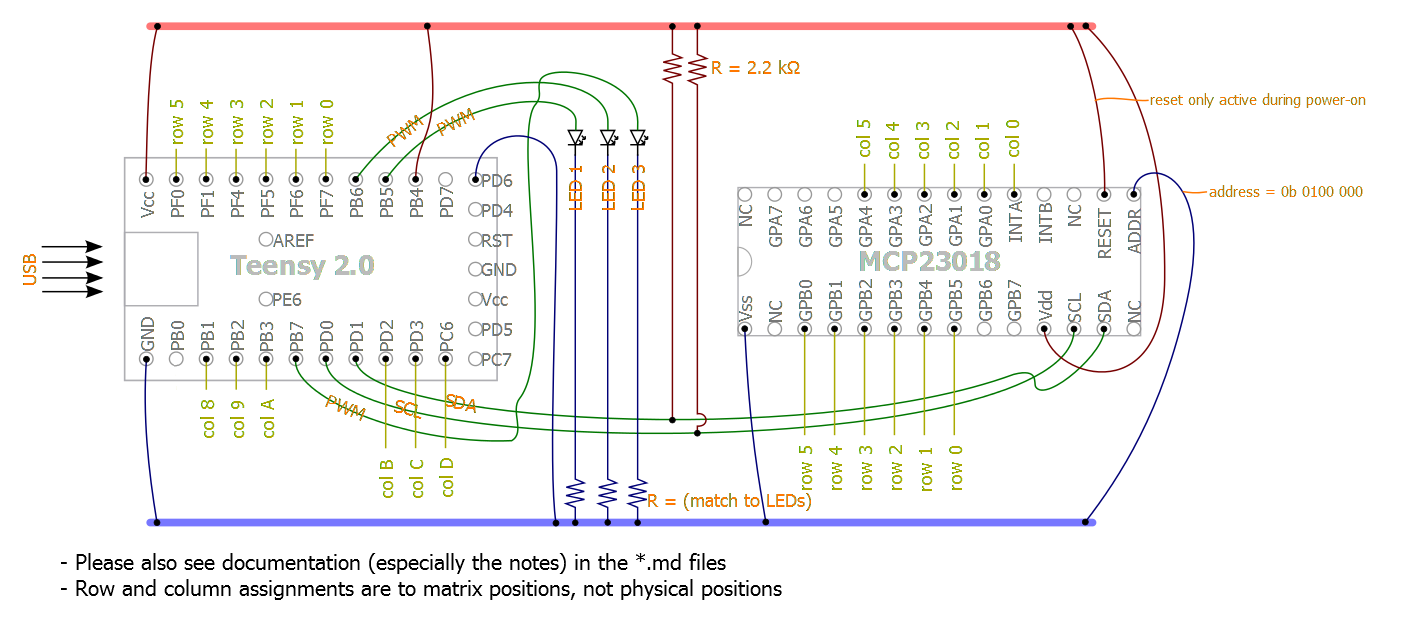
This next step is to wire the Teensy 2.0 and the MCP 23018 in place. Everything necessary for that really is the following circuit diagram.
Things to note here:
- The columns for the MCP go from 0 to 6, the columns for the Teensy go from 7 to D (counting in hexadecimal) which makes great sense, since the MCP is to the left of the Teensy and we read from left to right.
- When debugging this and using the ergodox-firmware, both sides have to be wired completely and actually with the TRRS connected. Don’t expect the keyboard to work before that. The reason is that the ergodox-firmware stops completely if either the Teensy or the MCP weren’t initiated properly.
- The LEDs are handy for debugging; definitely go ahead and connect those. When the keyboard starts successfully two of the LEDs light up shortly.
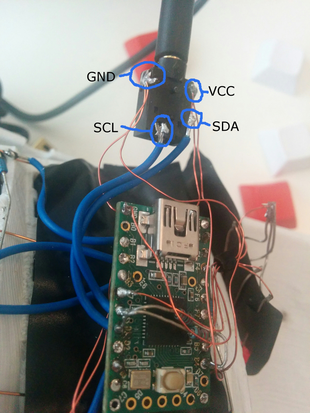
- From the Teensy over to the MCP go exactly 4 connections. The blue, the red and the two green ones. This is done using the TRRS jacks and cable.
- Yes, the connection from B4 to VCC doesn’t seem to make any sense, but the B4 port actually gets used directly in the ergodox-firmware, so just connect those connections that make no sense on first sight and either don’t question it or find out why this is necessary by going through the firmware in great detail.
This is how the trrs jacks are wired:
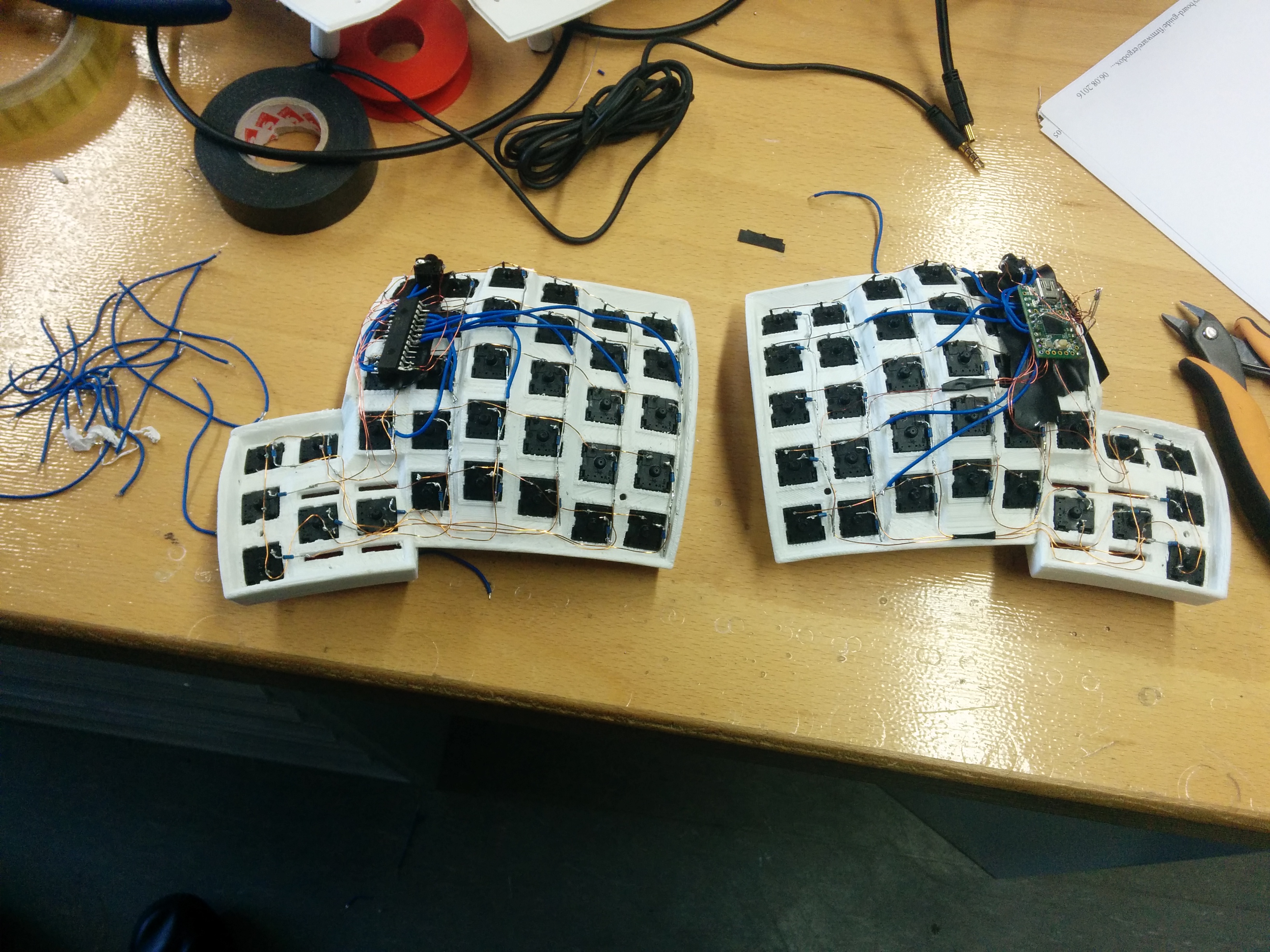
After you are done you might have the following result:
Good luck!
