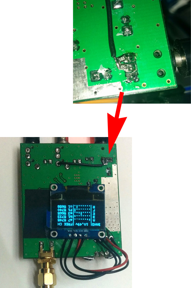
rx5808 5.8ghz SPI scanner with display This repository is a clone of [OLED-scanner] (https://github.com/MikyM0use/OLED-scanner) by MikyM0use/OLED-scanner
- support 240*240 TFT IPS SPI display
- support rotary encoder instead of buttons (not implemented)
- add L band to support 48 channels (not implemented)
(per il testo in italiano, cliccare qui) (for the italian version of the text, please click here)
This scanner/receiver is aimed (but not limited to) FPV quadcopter race addicted.
When many people need to use video channels over 5.8ghz the interferences become a problem, not only because of the superposition of two or more transmitters, but also to the harmonics of the transmission frequency or the distance between different TXs. So it's useful to have a simple indication of channels (frequency) current usage.
The goal of this project is to develop a simple "scanner" that measures the RSSI (Received Signal Strength Intensity) of each 5.8ghz channel, using this information to determine free and used frequencies. The hardware needed for this project is:
- An RC305 receiver with SPI-modified module (see below) (any RTC6715-based receiver, like the RX5808, can be used). Please notice that the "receiver" functionalities will not be lost! the RC305 will become a 40CH with autoscan receiver.
- An Arduino (I used a PRO mini, but any ATMega328p will be ok)
- A cheap OLED 0.96'' display
- some electronic components (see below)
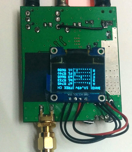
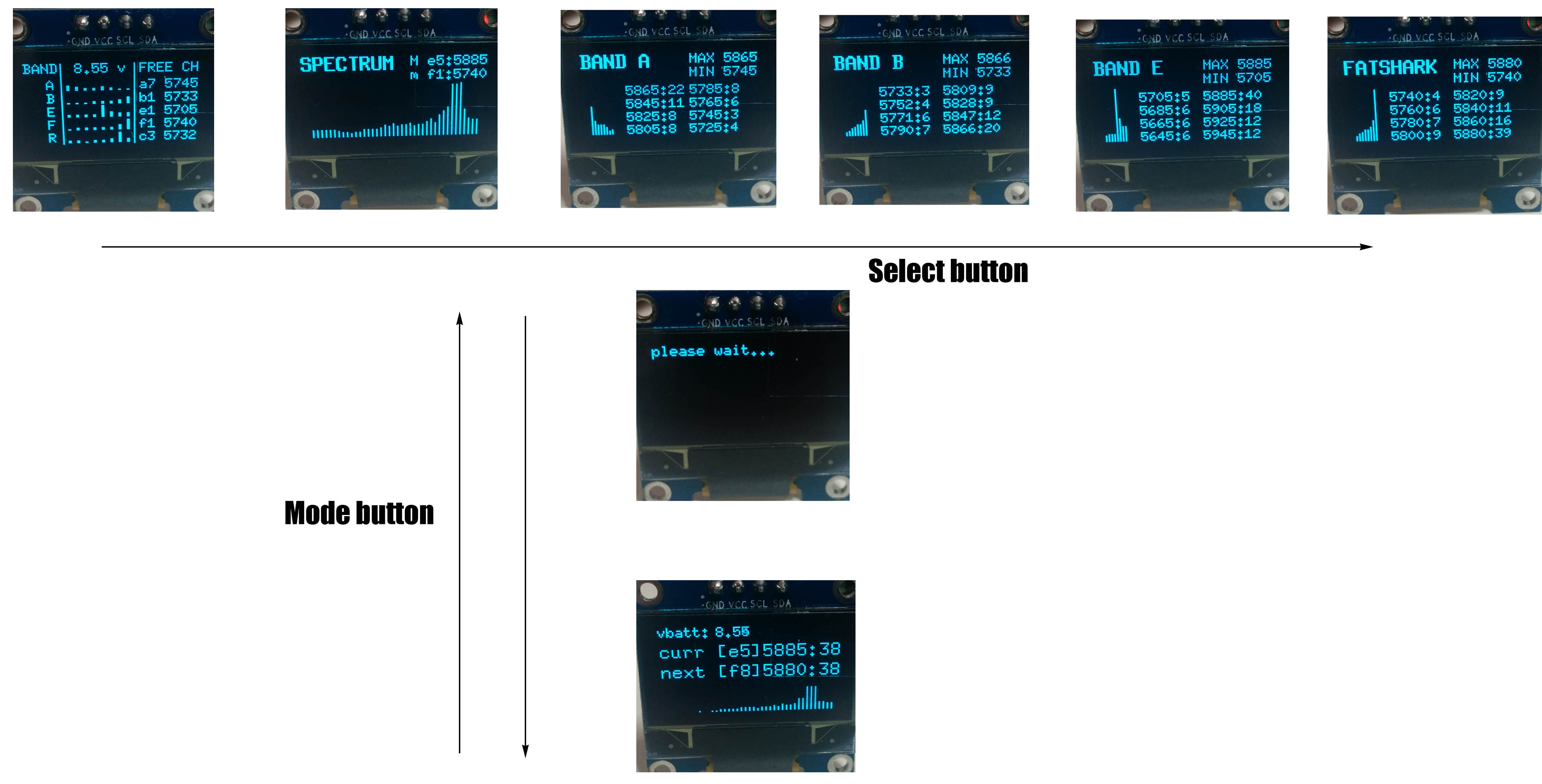
##Some (preliminary) pictures of the "scanner mode"


##A picture of the "receiver mode"

##Similar projects:
Deluxe 5.8GHz (rx5808 module) control based on arduino with TV out.
universal FPV receiver module by bollop80.
Stages to success:
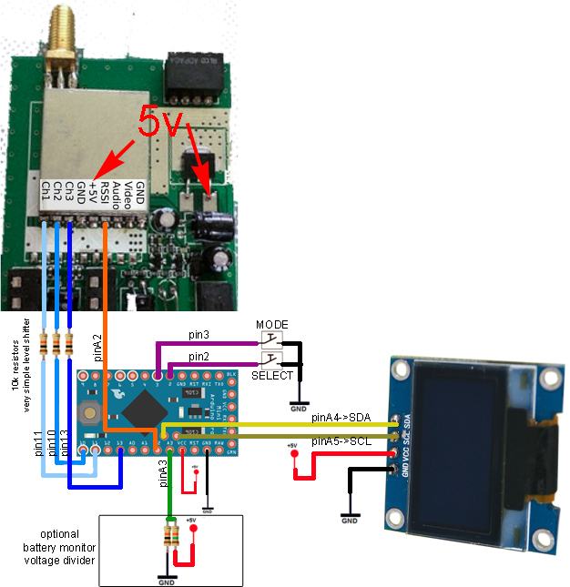
##Connection diagram hope this image is enough for the moment, sorry!
Actually it's possible to use any value for the 3 SPI resistors in the range of 1kohm-10kohm. For the voltage divider I used 15Kohm and 10Kohm resistors, but any 1/3 divider should work (see section Voltage divider).
Notice that to power the arduino and the OLED display you have two different options (see the red arrows in the picture above):
- take the +5v and GND directly from the pin of the RX module like I did
- use the linear voltage regulator of the RC305
DO NOT use directly the DC input of the RC305 unless you know that you are actually bypassing the voltage regulation step.
##STEP 1 - RX SPI mod
On the RC305 the frequency is changed by using a series of dip switch, but it would be useful if we can change the frequency via software... luckly, the RX module is based on the IC RTC6715, which allows us to use an SPI protocol to change the frequency. But Before that, we need to explain to the RTC6715 to get rid of the dip switch. This is accomplished by removing a resistor inside the RX module...
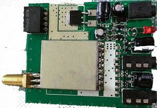
First of all, you need to open the RC305 module, it will be similar to this:
next, carefully remove the RX module shield
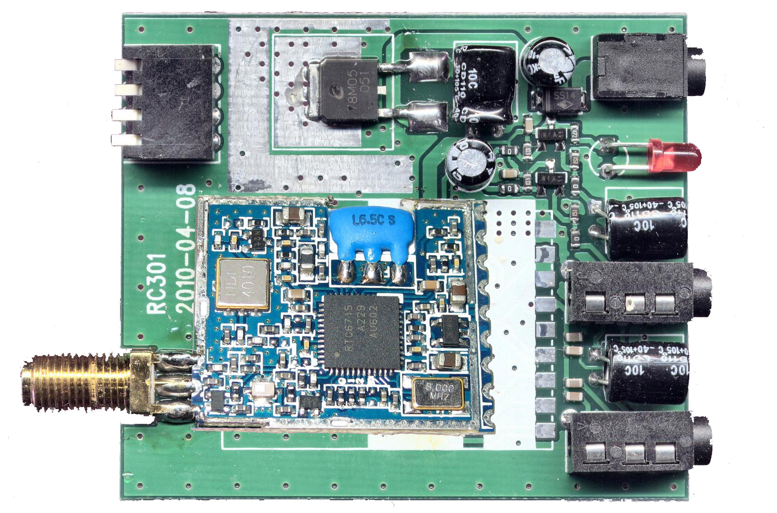
next, remove the resistor marked by the arrow
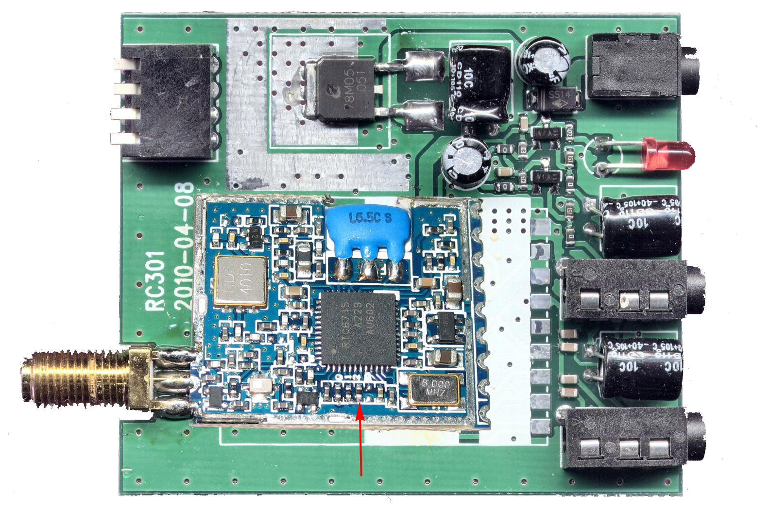
next, close all again.
##STEP2 - Arduino connection
This is the more creative step... follow the image in the [Connection diagram](Connection diagram) section and connect the Arduino and the RX module. Remember that since Arduino is 5v powered and the logic levels of the RX modules are 3.3v you need a level shifter (maybe better than mine!).
It's important at this point to desolder the dip switch or at least cut the trace on the back of the board!
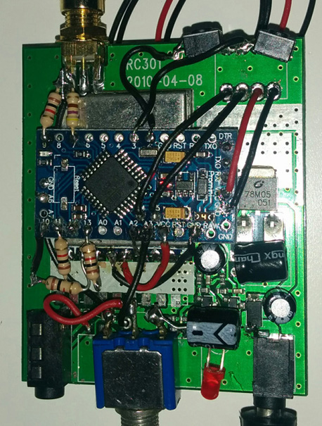
Just to let you get an idea of the result, this is what I've done, but keep in mind that this includes some other not-documented mods (I'm working on the TV out for the next release)... and yes, it's a mess full of trying/retrying/solder/desolder :)
##STEP3 - Voltage divider This is an option to get the voltage of the main battery (that can be a 2s or 3s lipo). I think that the simplest solution is to solder a couple of resistor (15k and 10k ohm) directly on the input jack connection...
##SOFTWARE section There are basically two modes of functioning, "scanner" and "receiver". In the first you can see the RSSI of each band, the spectrum and a summary of the channels usage, while in the "receiver" mode, the scanner acts like a normal RX with autoscan feature. This is the list of the different screen you have on the scanner mode and on the receiver mode:
The scanner MUST be calibrated before use. Calibration procedure is simple: just switch on a vtx couple of meter away from the scanner, then turn on the scanner while pushing a button (no matter which one) for couple of seconds. You will see min/max RSSI and the calibration is over ;)
##Donations:
Hardware or paypal donations to carry on the project are always accepted.
