O-LAP is an umbrella term for a couple of things.
It is an open-source set of tools to build parameterizable models of flat-pack style furniture.
It is the community of people that designs such furniture.
It is the name of a design style that uses computer technologies at the core of furniture design.
Read the vision page.
O-LAP follows a decentralized way of running things. The designs are logic written by the designer in Javascript which is displayed to the user by fetching the code from the designer's repository and running it in the user's browser. The designs and data themselves are maintained by each Github repository holder (and Github of course).
If you are interested in the concept, start by making a design.
There's a lot of information about parametric furniture.
Check out one of our articles on its creative use.
Read the quick-start to learn how to start.
Submit your design.
Community admins ensure that designs fulfill the requirements as set by the design guidelines.
The design information is used to display information about the design in the gallery.
Design.info = {
    "name": "Boxy",
    "designer": "Roxy",
    "version": "1.0.0",
    "short_desc": "Template design file demoing project setup.",
    "long_desc": "",
    "url": null,
    "tags": [ "", "" ]
}
This is used to render information about the design in the gallery and wherever else the relevant information is required.
name: Used as the design display name.
designer: Name to be used as designer.
version: Like software, the code that generates your design can change overtime. You can use the version number to capture that as your design moves forward.
license: Specify what license type you wish to apply for your designs.
short_desc: Used to show short descriptions of your design wherever needed. Less than 140 characters.
long_desc: Used to give a more detailed description for your design. Less than 2000 characters.
url: Used to point to any external link you can maintain for your design.
tags: You can add upto 10 tags for your design.
message: Displayed in the UI to explain anything you may want about the parameters.
The starter_project has files in place to let you run and test your design in a development environment and once you push it and register it with the main app, it runs smoothly with the framework as well.
- design
  - Design.js
  - display.jpg
- olap
  - css
    - materialize.min.css
    - style.css
  - js
    - materialize
      - init.js
      - jquery-3.3.1.min.js
      - materialize.min.js
    - three
      -	Detector.js
  	  - mode.js
  	  - OBJExporter.js
  	  - OBJLoader.js
  	  - OrbitControls.js
  	  - three.js
  	  - threeScene.js
  	  - THREEx.FullScreen.js
  	  - THREEx.screenshot.js
      - THREEx.WindowResize.js
  	  - verb.js
  	  - verbToThreeConversion.js
    - OLAPFramework.js
- dev.html
- README.md
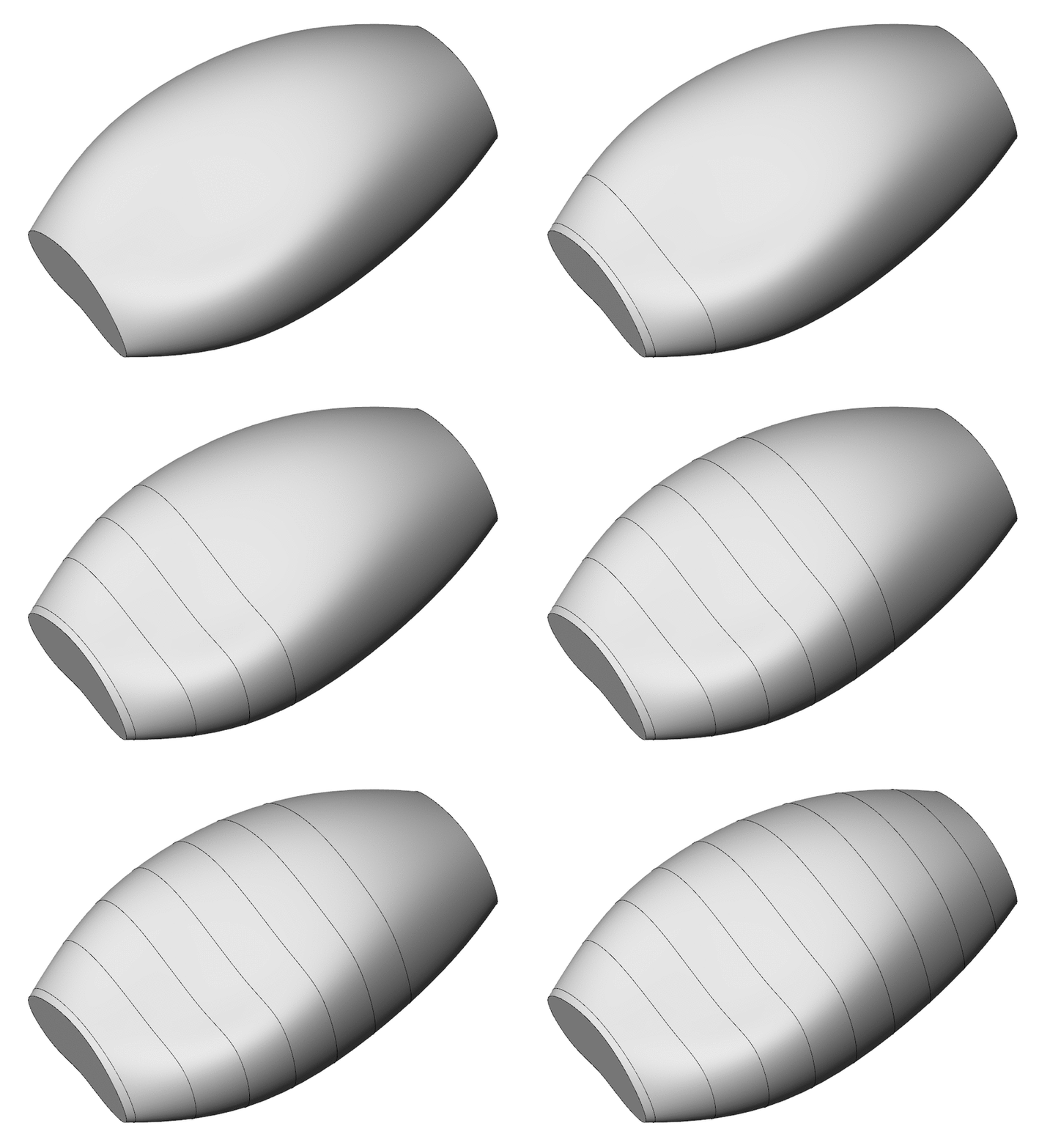
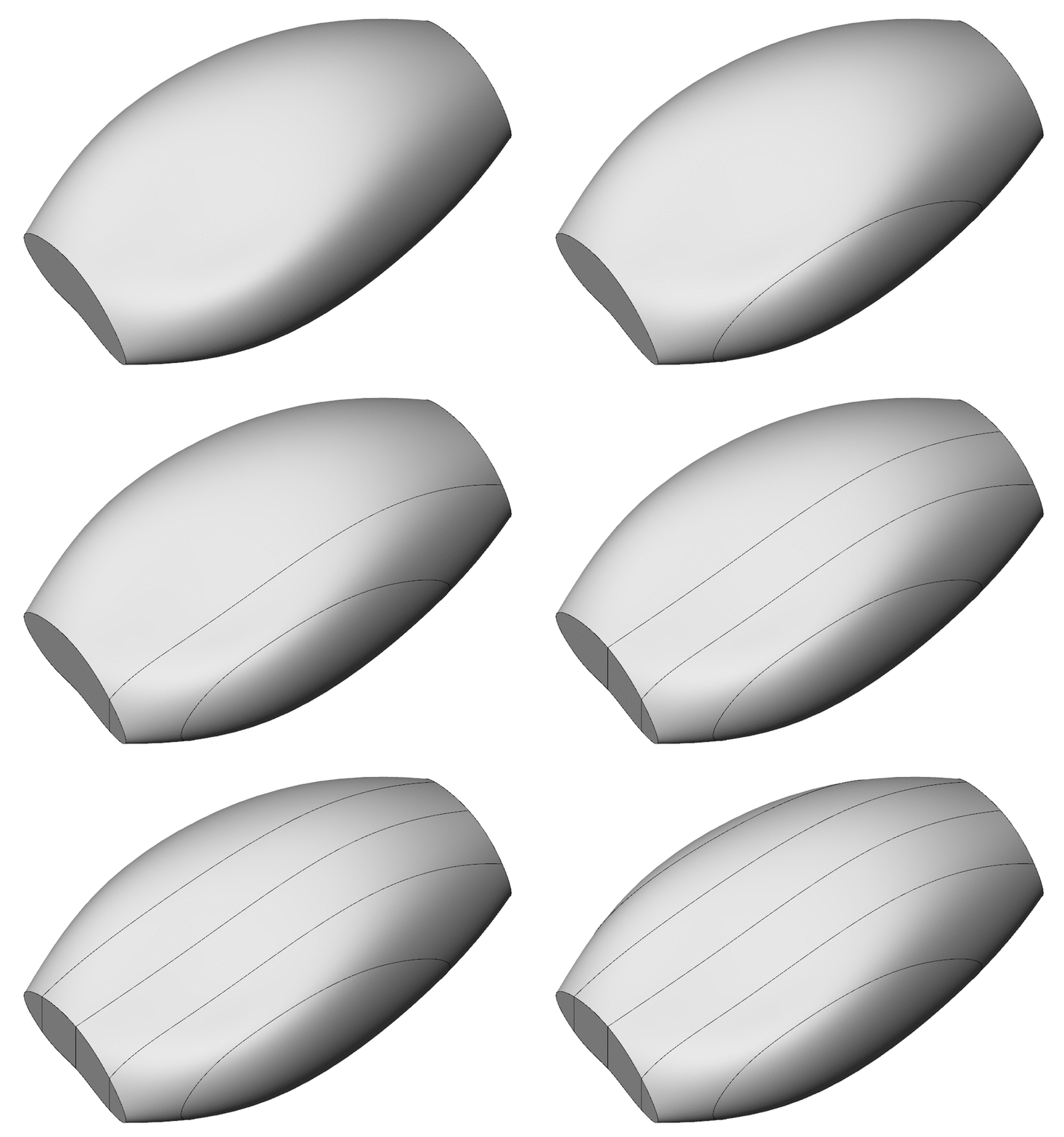
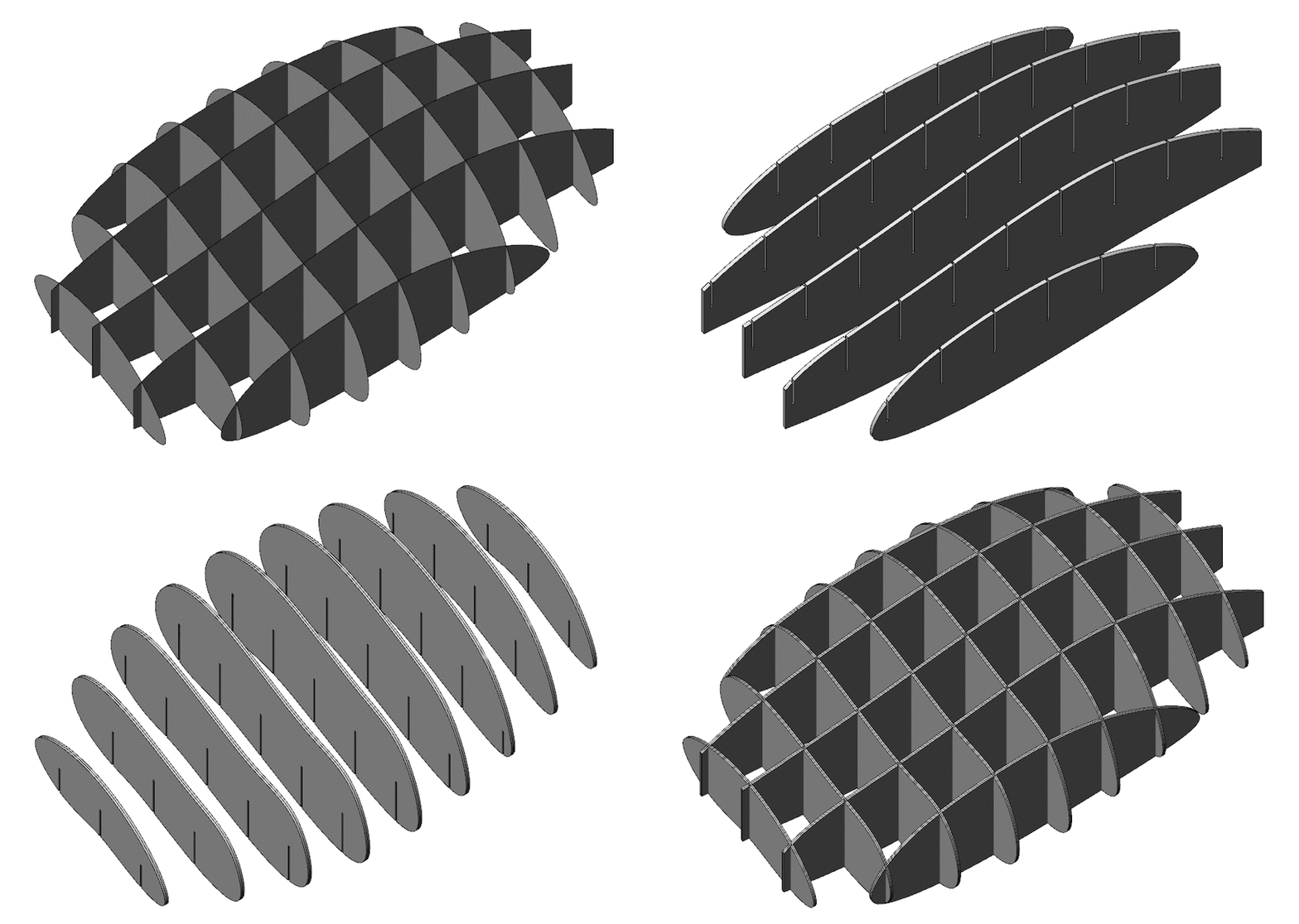
Slicing is the process of converting the solid design into these waffle strcutures.
Cutting slices out of the geometry in first direction.

Cutting slices in the other direction (perpendicular to the first direction).

When the two sets of slices are overlapped with each other they create the load-bearing waffle structure.

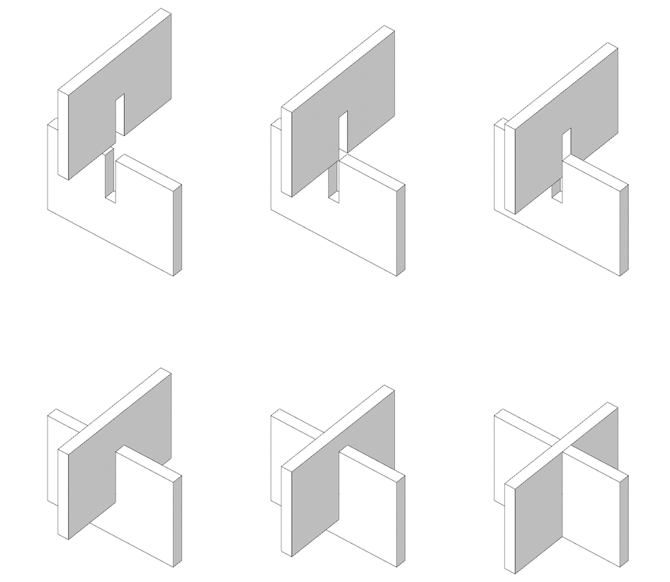
The slice sets have grooves in the opposite directions where they intersect to the pieces to overlap and slide into each other.

O-LAP slices and creates the CAD drawing for any design.
ThreeJS library is used to render all geometry and you can put anything that is compatible in a THREE.Object3d object into group. Since the designs have to be cut and fabricated you would need to make sure that the designs are geometries which are suitable for such a process.
The slicers are also procedurally added so you can change the slicing behaviour as the design changes. And you can have more than 2 of them.
The cuts are made vertically and the grooves used for interlocking are represented as single lines and distributed in exact halves for each cut direction.
This should allow interlocking for all ground touching elements. Parts which don't touch the ground need more thought and the slices need to conform to certain rules to make sure they can be fabricated.
Refer the design guidelines for more information about slicing.
The sliceManager is a special object passed into the updateGeometry method of a design file, to allow the you to specify how the design is to be 'sliced'.
You slice the volume in two perpendicular directions with half length cutouts in each of them to allow the other piece to slide in.
You can use the addSliceSet(config) method to add slicers for the design. The cuts are made vertically and all designs are expected to have atleast 2 slice sets which are perpedicular to each other. The main consideration while determining the slices should be weight distribution and strength as these are load-bearing elements of the furniture design when fabricated.
The configuration object must carry the following information for slicing.
    uDir: true/false        // direction of the cut, aligned to the world XY axis
    start: number           // the start coordinate position in the axis specified
    end: number             // the end coordinate position in the axis specified
    cuts: number            // number of cuts to be made along the axis (minimum 2)