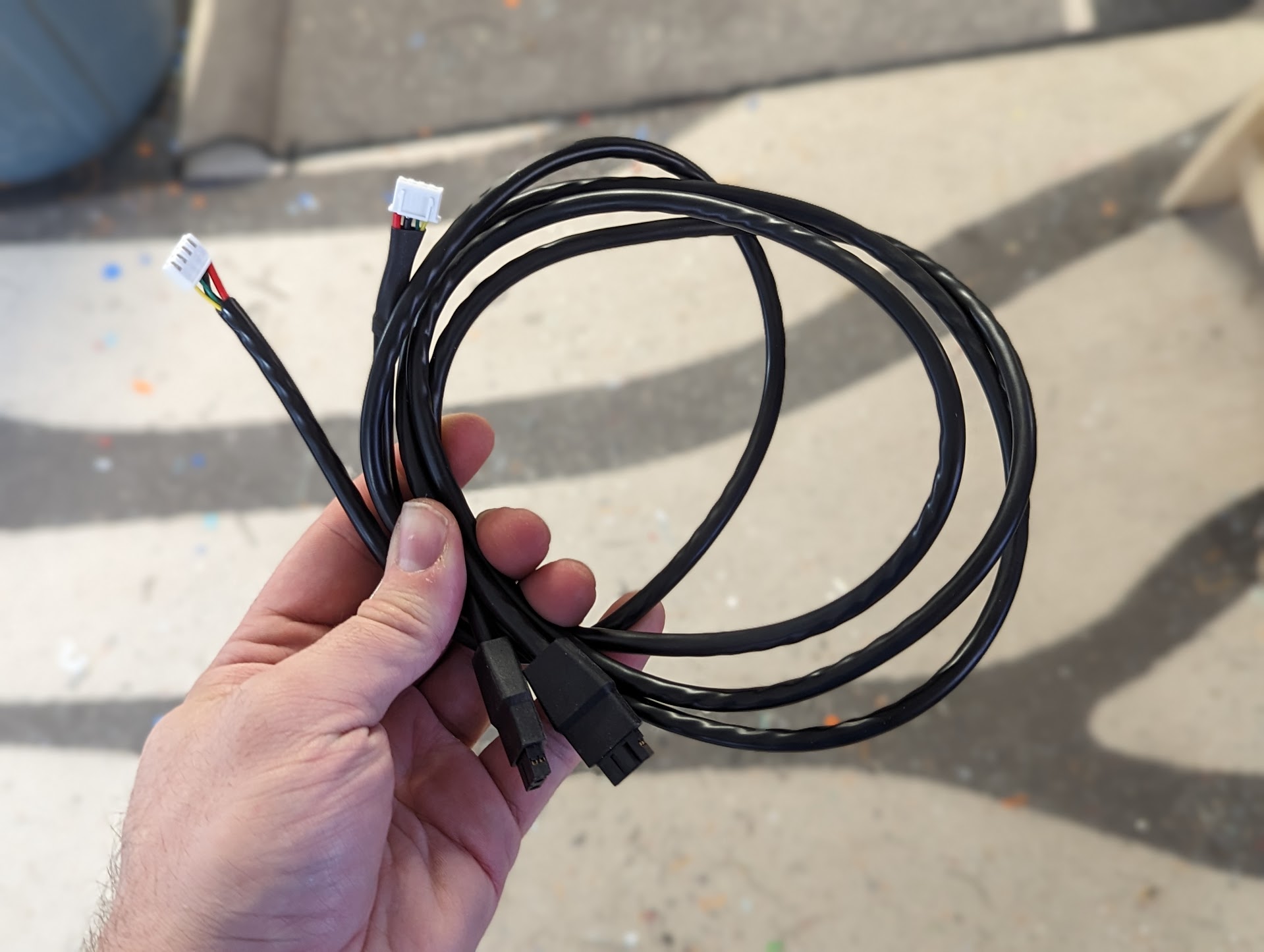
There is no requirement to use Canbus with TapChanger, but it's the most supported method right now. Alternatively each toolhead can be connected via USB or have a big fat wire cable to a controller board that supports multiple extruders.
Canbus is essentially a mini Ethernet, over a shared wire pair. Each node is connected in parralel.
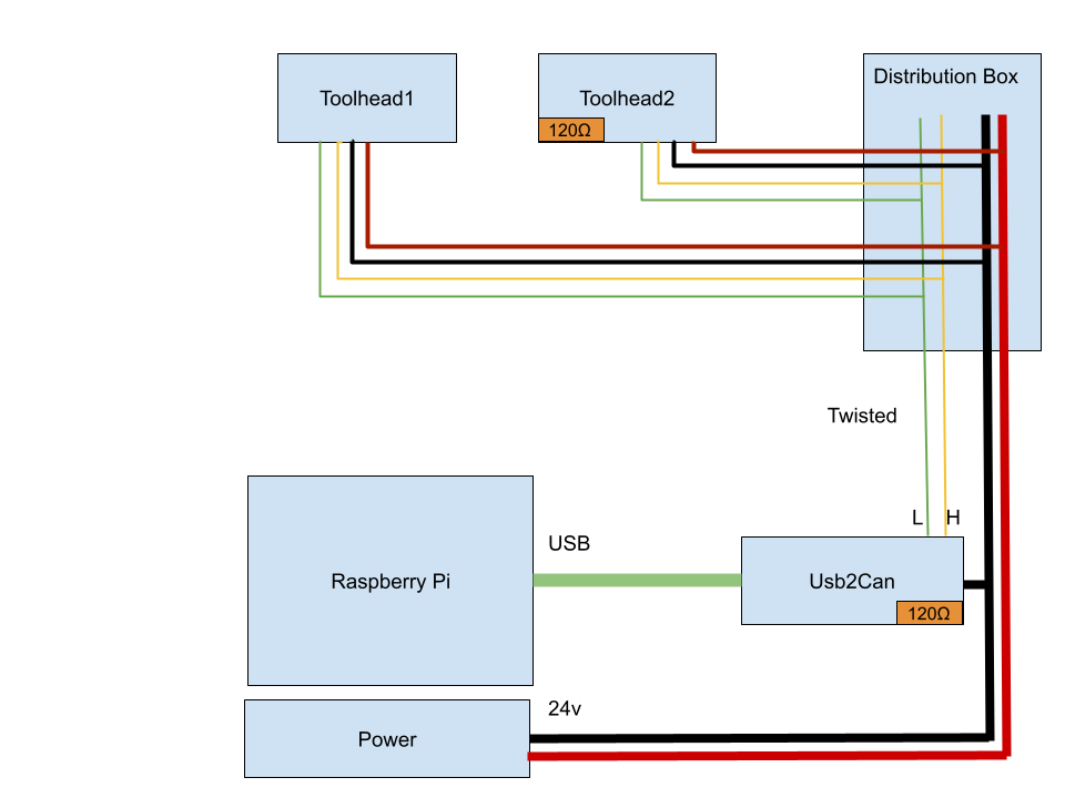
This is the overall layout we are using for wiring:
Each extruder gets:
- Ground and +24V
- CanL and CanH
CanL and CanH wires need to be twisted togeteher. Premade Canbus wire harnesses are available, but distances we are using here are very small and just manual twisting is fine.
Calculate your max load across all hotends, and make sure that the wires from the distrbution box down to PSU can handle that. The heaters are typically controlled with 100ms power cycle that means that even if they are all on 10%, they will be on at 100% at the same time for 100ms at a time which is enough to brownout your PSU. I had very wierd Canbus glitches that came down to voltage drops when all heaters are on.
Maybe one day Klipper will support power cycle staggering making this less of a problem.
Canbus supports a range of speeds up to 1mbs. We are using an unusual topology with fairly long branches from from the main bus, which causes extra signal reflections. There are quite a few data sheets describing the maximum branch length for each speed, I have seen very conservative saying 30cm max for any speed to very relaxed of 1.5M for 1mbs.
Our branch length from the distribution box is approx 60cm. That definately seems iffy for 1mbs and seems confortable for 500kbs. That is what I'm running. And getting about 5% utilization running two tooleahds so seems plenty of headroom.
There are several extruder boards that are specifically designed for Stealthburner. Most notably EBB SB2209 from Bigtreetech and SB2040 from Mellow fly. I have had good success with both.
Similary for Mini stealthburner there are smaller versions available, like EBB36.
All of those boards can be used either in Canbus or USB mode, changeable by flashing the appropriate firmware. If you are uncomfortable with Canbus, and fine with running two more wires to each hotend, you can use USB mode with a USB hub.
The flashing and setup process of those boards can be a bit involved, the manufacturers instructions are okay, but genereally require a Windows machine to follow. There are some instructions out there to flash directly from Raspberry.
Raspberry pi does not support Canbus directly, there are a few options what to use.
This seems to be the most reliable option. But costs extra and occupies a USB port on your Pi
To enable this, you need to flash Klipper with U2C enabled. If your board supports this, there should be a guide for that.
In my experience this can be a bit unreliable. Your main controller board is also now connected via CanBus and now needs to drive 6 more motors and bunch of fans and thermistors. This leads to about 50% of bandwidth saturnation with 500kbs.
I did see occasional probe move timeouts with it so moved to a dedicated Usb2Can board instead.
Are a Raspberry PI hat boards that use the GPIO pins instead of USB. Should work just fine, have not tired though.
My rule of thumb: Sum up all your hotend heaters + ~10w on top for each hotend + ~100w for the rest of the printer (assuming mains heated bed).
I'm running oversized 12gauge cables from distribution box to PSU. Mainly because the next ones I had around where significanly thinner.
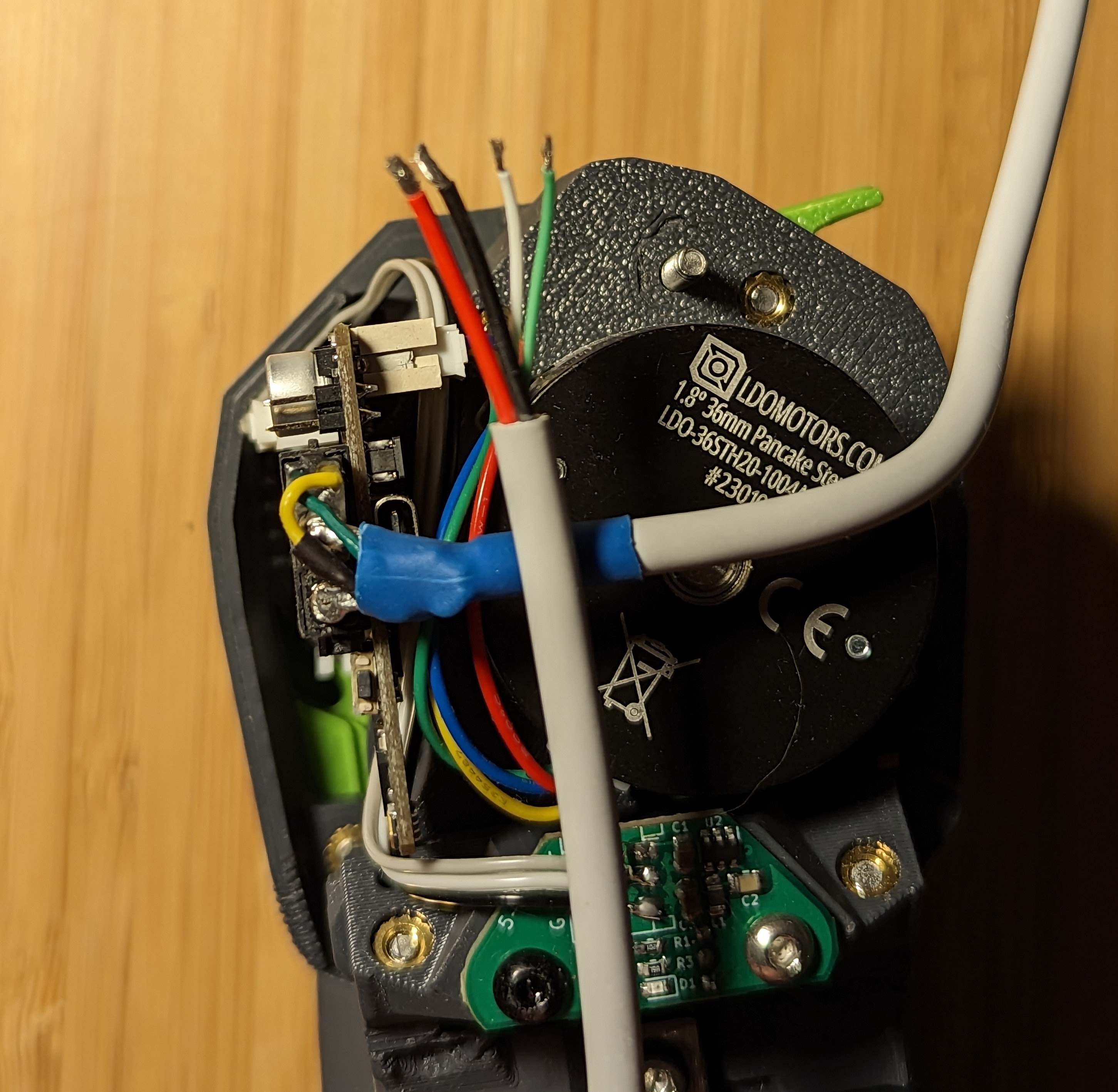
And running USB C charging cables from hotend to the distribution box. Get ones that are arvertised for 100W charging. They are supposed to handle 5A sustained. That is 120w - more than enough for most hotends. Rapido or other 100w+ hotends are a bit marginal. The USB cables are significantly more lightweight and felxible than premade Canbus harnesses and with Silicone sleeving should survive long enough. USB data cables are also twisted pair, making it a nice match.
For Distribution box to Usb2Can, I just manually twisted together two wires.
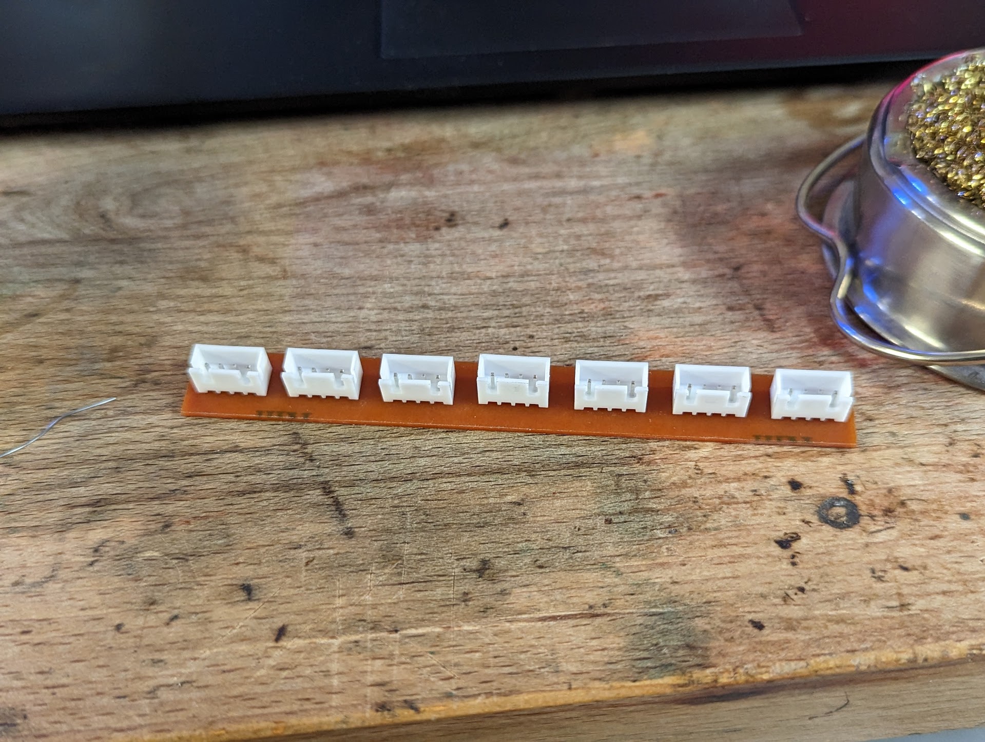
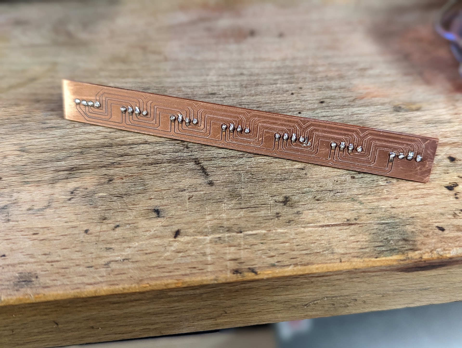
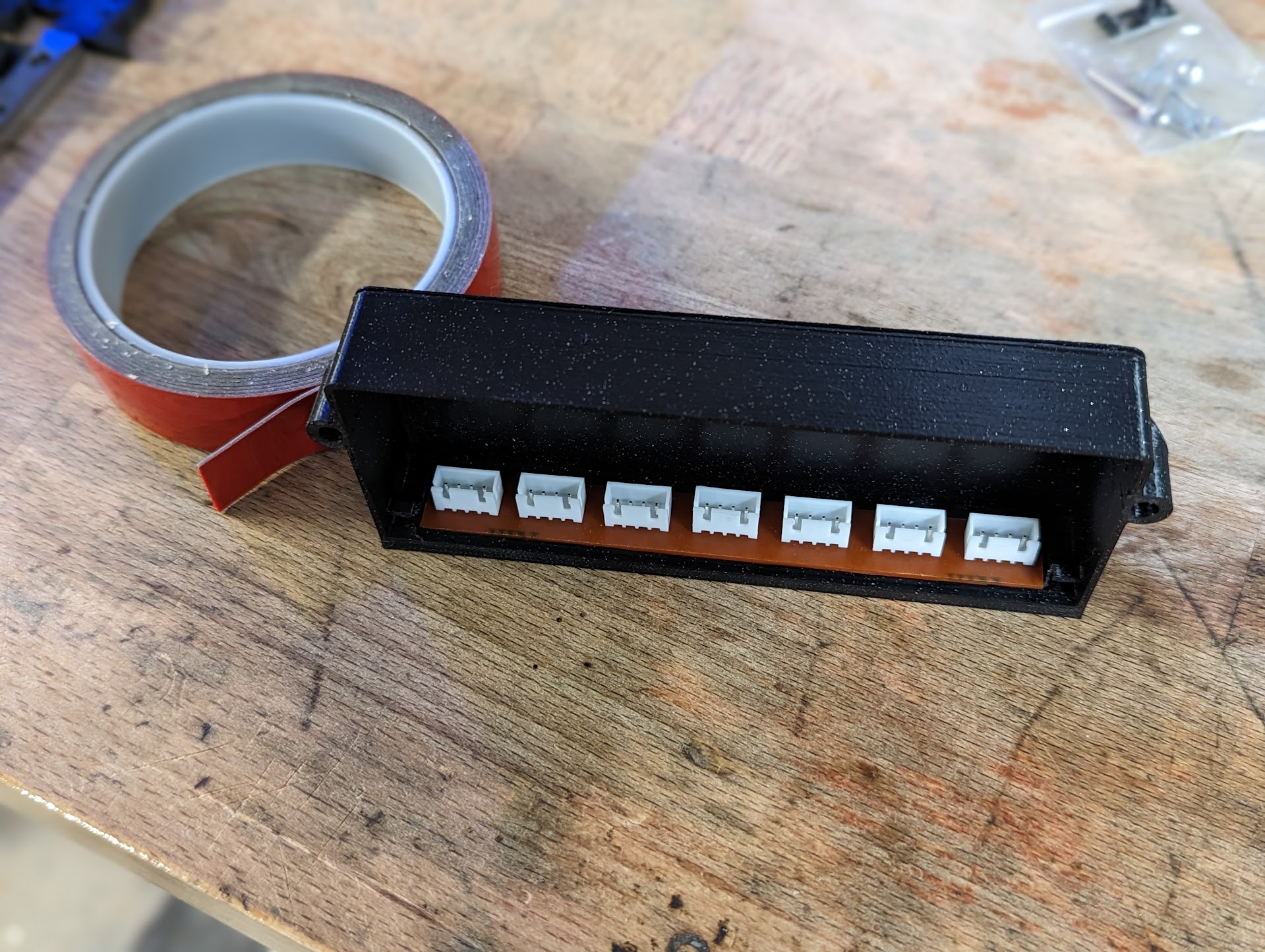
The electronics folder contains a PCB that can be used to connect the canbus cables together. It has 7 connectors: one to your controller board, and 6 for extruders. The PCB itself can be ordered online (e.g. from PCBWay, by uploading Distribution_Board_cam_output.zip which contains gerbers). It is meant to accomodate 4-pin JST-XH male connectors (e.g. these from amazon).
For a voron 2.4 350mm build, cutting the cables to 1 meter in length should be long enough to go from the toolhead to the distribution board. If you are using BTT SB2209/SB2240 boards, they come with a wire long enough that you will have spare length to connect the distribution board to your controller as well. Simply crimp the female JST-XH connectors with a crimping tool like this one.
Use some double-sided tape and fit the board inside the distribution box:
