The body is the housing of all the electronics for the rover. It is the attachment points for the rocker-bogie systems, as well as the differential pivot system.
- Gives passthrough connections for USB ports on Raspberry Pi
- Cutouts on the rear of the body give access for voltage monitor and battery for charging
- Easy attachment point for differential pivot system
- Uses Actobotics parts to facilitate modularity and ability to change, and add new components easily.
| Author/Creator | JPL |
|---|---|
| Cost without 3D printer | 253.28 |
| Cost with 3D printer | 240.38 |
| Date Added | 4/11 |
| Group/Organization/School | JPL |
| Time to build | 3 hrs |
- Band Saw/Dremel
- Band saw or Dremel
- Allen Key set
- Imperial Wrench Set
- Laser cutter
- None
- 0.5 Inch aluminum rod into bearing blocks on rocker-bogie arms
- 0.5 Inch aluminum rod into clamping hub on differential pivot
Note: ServoCity has discontinued the 12x9 aluminum plates. Designs for replacement plates are available in the laser_cut_parts directory. If you need to use the laser cut parts, read the information found in laser cut parts/README.md and then skip to section 3.2 of this document. The laser cut replacements have the necessary holes.
| Item | Ref | Qty | Image |
|---|---|---|---|
| 9"x12" Aluminum Plate | S35 | 1 |  |
First we need to drill a hole in one of the 9x12 Aluminum plates S35 because we will need a hole of just over 0.5 in diameter for the differential pivot mount. There is already a small hole drilled in the location we want to use, but it needs to be widened substantially. Start with the drill #23 and drill the hole shown by Figure 1. Repeat this with drill sizes stepping up until you get to a drill of 0.5 in.
Take the 0.5 in hollow rod S19 and make sure it spins freely in the hole you have created. If it does not, drill the hole slightly larger or sand/file the hole until the rod spins with no resistance (The 0.5 in hollow rod must spin freely while mounted inside the bearing blocks. See step 2.2 Differential pivot for example. It may help to follow step 2.2 in this document to test if you have enough clearance)
  |
|---|
| Figure 1: Drilling the Aluminum Plate |
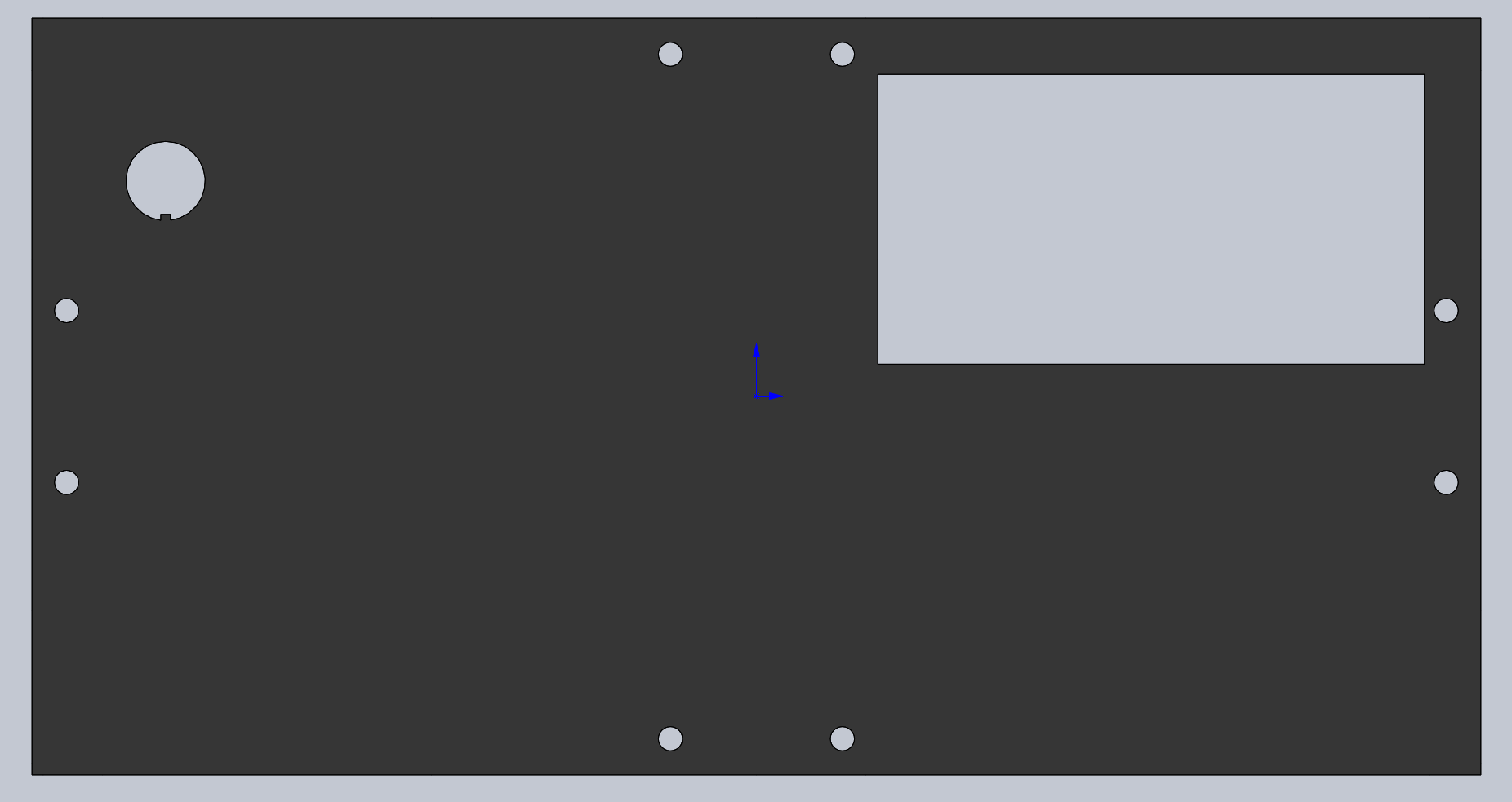
The front and back panel of the rover are designed to be made from laser cut acrylic, as to keep them modular to design different things to mount there as wanted. The 2D cutout files are the .DXF files and can be found on the github under Mechanical - Body Assembly - Laser Cut Parts
If you do not have access to a lases cutter there is an online service which you can order these from below: https://www.sculpteo.com
To get the above parts from Sculpteo, go to Laser cutting and then upload these files (with mm selected as units). Hit Next. Make sure scale is set to 100%, change the material to Acrylic, have thickness to 1/8 inch, and then select whatever color you wish.
DISCLAIMER All images were created using CAD that has #6-32 Socket head cap screws, but the parts list calls for button head screws. The button head screws are correct.
Take the modified 9x12 Aluminum plate S35A and attach the four Dual side mount A S17 using screws B1 at the locations shown below. Take care to match the orientation shown.
  |
|---|
| Figure 2: Attaching side mounts to top panel |
Attach the 4.5x12 plates S37 to the dual side mounts using screws B1
  |
|---|
| Figure 3: Attach the side panels |
- Insert the #6-32 Heat Set Inserts I2 into the 3D-printed clamping hub S50 in the locations shown in Figure 6. The inserts on the side of the clamp should go in from the left side as shown in Figure 4.
- Using washers W1, insert screws B4 into clamp part of the clamping hub and screw part of the way into the brass inserts. Inserting these screws now simplifies inserting the PVC pipe later.
  |
|---|
| Figure 4: Assemble PVC Clamping Hub |
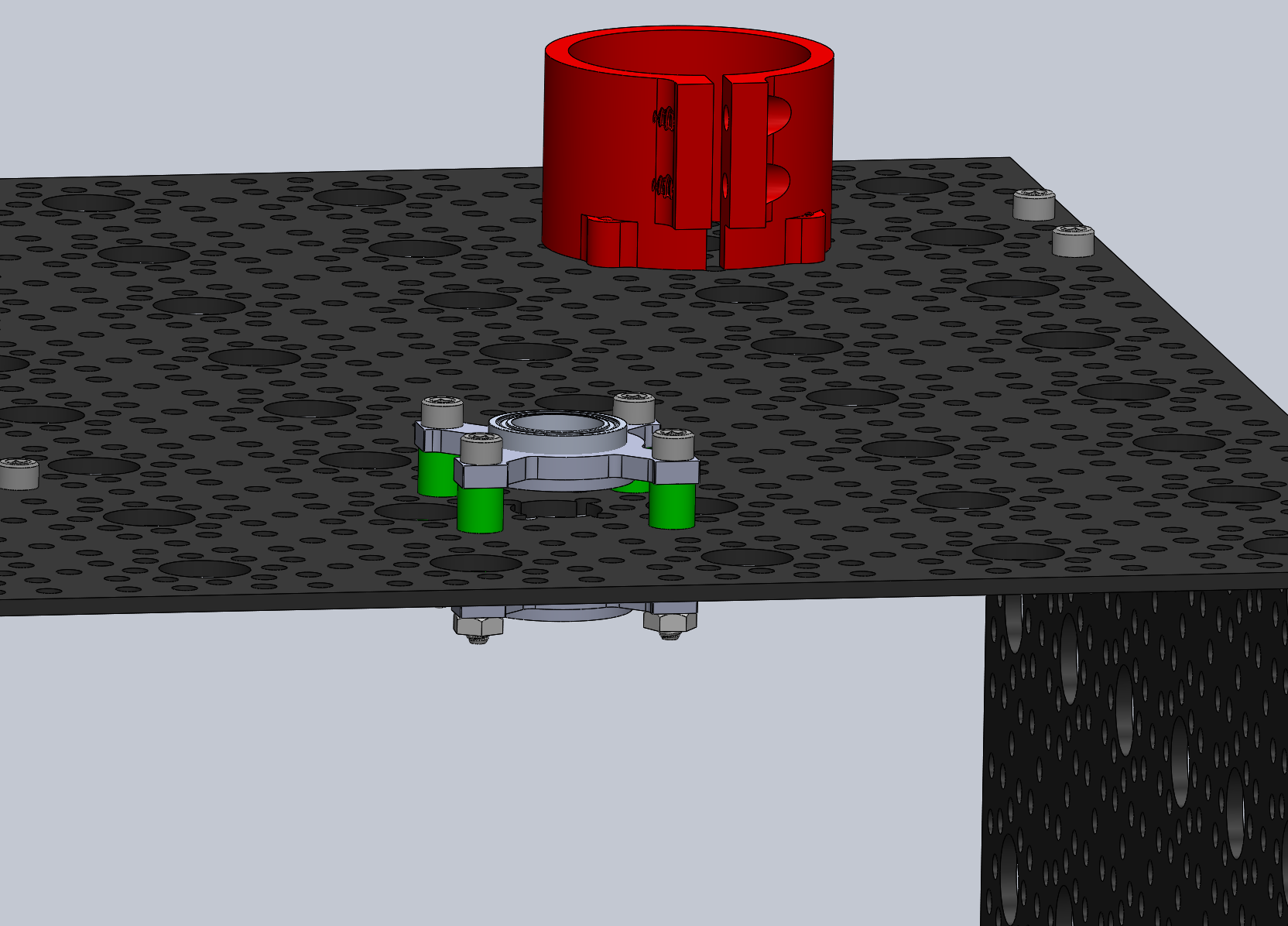
Attach clamping hub S50 to the top plate of the body using screws B1 Use the location shown in Figure 5.
  |
|---|
| Figure 5: Attach the PVC clamp to top plate |
The differential pivot is used to transfer weight off of the wheel that is currently climbing to the other front wheel, allowing the rover to climb more easily. Additionally, it serves as a second contact point for the rover’s body such that it does not rotate freely about the cross rod.
| Item | Ref | Qty | Image | Item | Ref | Qty | Image |
|---|---|---|---|---|---|---|---|
| 0.5" Pillow Bearing Block | S11 | 2 |  |
#6-32x1" Button Head Screw | B6 | 4 |  |
| #6-32x1/4" Spacer | T1 | 8 |  |
Allen Key Set | D2 |  |
|
| #6-32 Hex nuts | B11 | 4 |  |
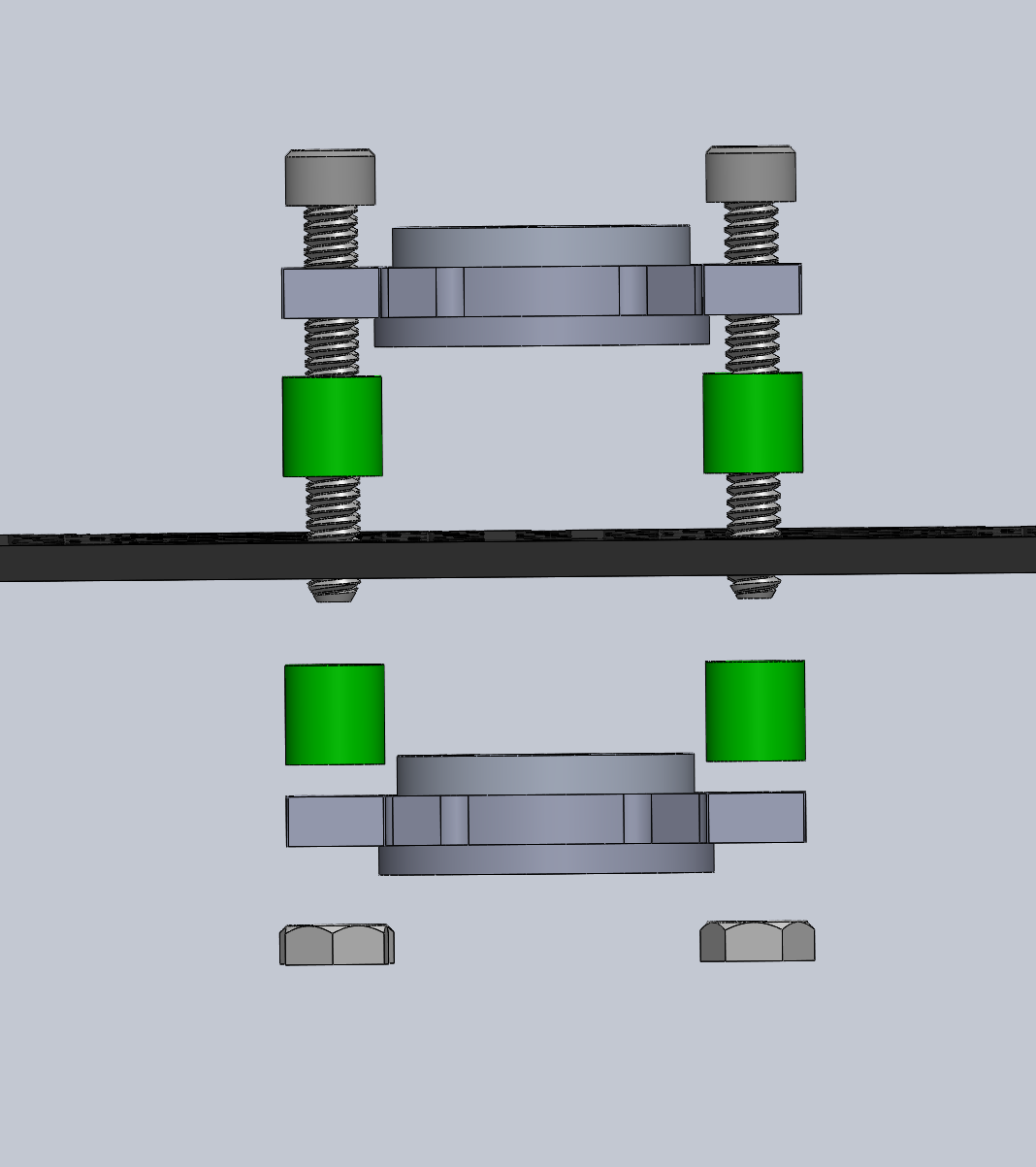
Using spacers T1, screws B6, and hex nut B11, mount the pillow blocks S11 to the top of the body over the hole in the aluminum plate that you drilled earlier as shown in Figure 6.
  |
|---|
| Figure 6: Mounting the pillow bloc |
| Item | Ref | Qty | Image |
|---|---|---|---|
| Assembled Control Board PCB | E1 | 1 |  |
| #6-32x3/8" Button Head Screw | B2 | 4 |  |
You may want to skip this step until the PCB is completed and tested and insert the PCB later.
Mount the PCB E1 to the top of the chassis using screws B2. Note the position of the PCB below.
  |
|---|
| Figure 7: Mounting the PCB |
 |
|---|
| Figure 8: Mounting the PCB |
Note the screw positions in Figure 8. You might not be able to get the screw circled in light blue in because of the PVC clamping hub. This is okay, install the other 3 circled in yellow.
Mount Dual Side Mounts A S17 using screws B1 on the side plates in both the front and back.
  |
|---|
| Figure 9: Dual Side Mount A locations |
Also attach Dual Side Mounts A S17 using B1 screws on the top plate, in the front and back
  |
|---|
| Figure 10: Dual Side Mount A (cont) |
Using screws B1 attach the front and back laser cut panels to the chassis.
  |
|---|
| Figure 11: Front and Back Panels attached |
Take the Volt Meter E38 and the Switch E39 and attach them to the back panel. Note that the switch goes in from the inside of the body, and the volt meter should snap press fit in from the outside.
  |
|---|
| Figure 12: Volt Meter/Switch Installation |
Take the 3D printed Battery holder S41 and using a solder Iron at 460 degrees F, push the #6-32 heat-set insert I2 into the battery holder as shown below.
  |
|---|
| Figure 13: Installing heat set inserts |
Mount the Battery holders onto the body assembly using screws B1 as shown in Figure 14.
  |
|---|
| Figure 14: Battery holder installation |
Take the 9x12 Aluminum Plate S35 and attach 6 dual side mount A S17 along the edges as shown in Figure 15. Be sure to verify that the orientation of the dual side mounts S17 matches the pictures.
 |
|---|
| Figure 15: Building the Bottom Panel |
Take the bottom plate assembly you constructed in the previous step and attach it to the chassis.
 |
|---|
| Figure 16: Attaching the Bottom Panel |
The Body Assembly is now Complete!
  |
|---|
| Figure 17: Completed Body Assembly |


