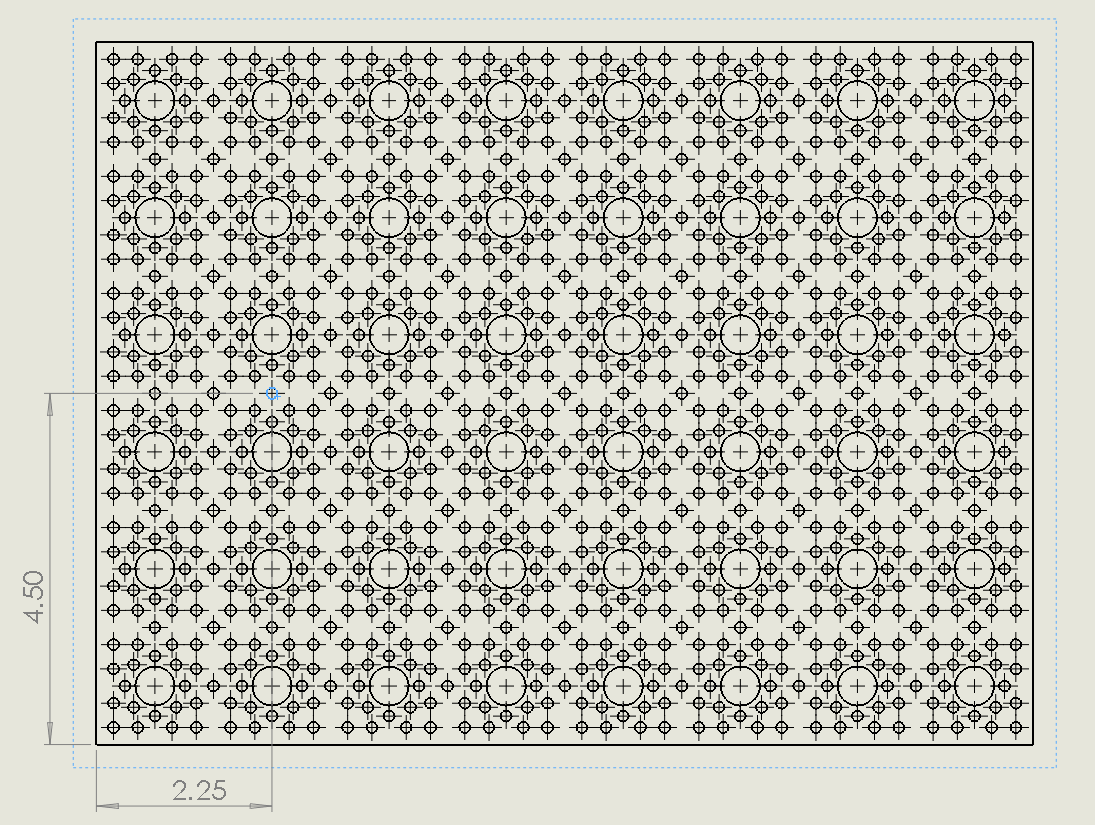
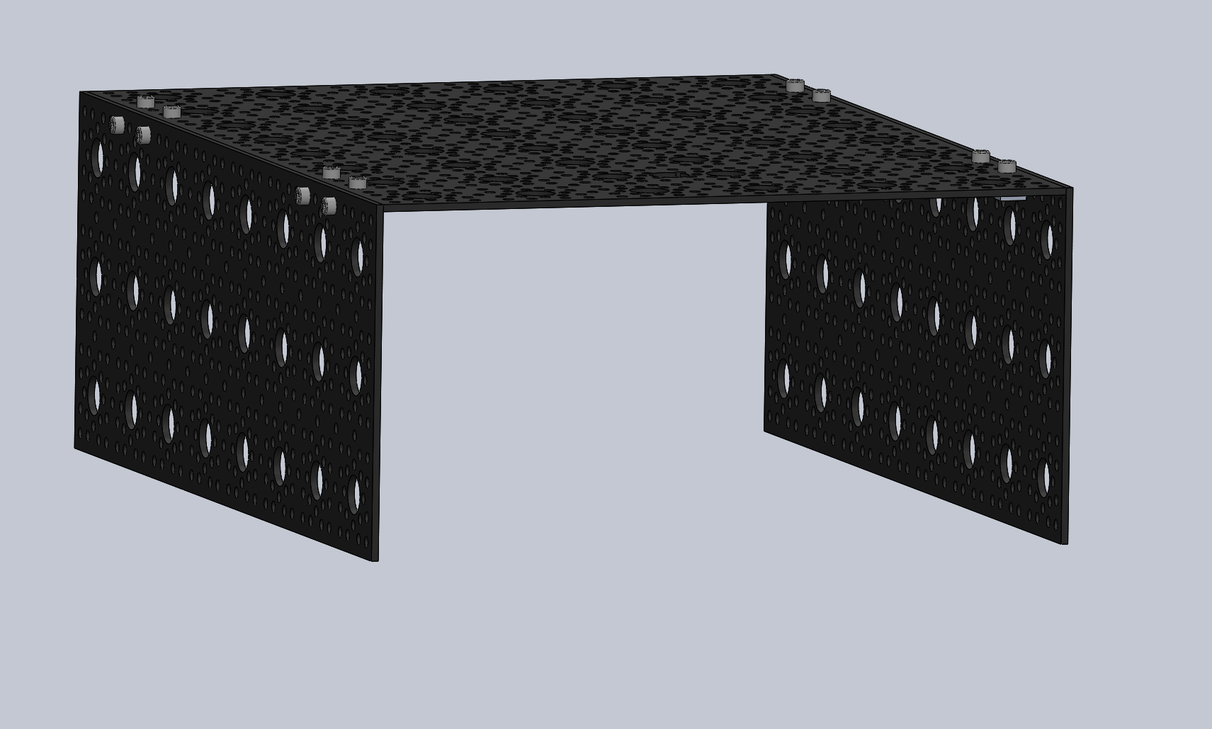
The body is the housing of all the electronics for the rover. It is the attachment points for the rocker-bogie systems, as well as the differential pivot system.
- Gives passthrough connections for USB ports on Raspberry Pi
- Cutouts on the rear of the body give access for voltage monitor and battery for charging
- Really pretty
| Author/Creator | JPL |
|---|---|
| Cost without 3D printer | 240.38 |
| Cost with 3D printer | 240.38 |
| Date Added | 4/11 |
| Group/Organization/School | JPL |
| Time to build | 3 hrs |
- Band Saw/Dremel
- Band saw or Dremel
- Allen Key set
- Imperial Wrench Set
- Laser cutter
- None
- 0.5 Inch aluminum rod into bearing blocks on rocker-bogie arms
- 0.5 Inch aluminum rod into clamping hub on differential pivot
| Item | Ref | Qty | Image |
|---|---|---|---|
| 9"x12" Aluminum Plate | S35 | 1 |  |
First we need to drill a hole in one of the 9x12 Aluminum plates S35 because we will need a hole of just over 0.5 in diameter for the differential pivot mount. There is already a small hole drilled in the location we want to use, but it needs to be widened substantially. Start with the drill #23 and drill the hole shown by Figure 1. Repeat this with drill sizes stepping up until you get to a drill of 0.5 in.
  |
|---|
| Figure 1: Drilling the Aluminum Plate |
Some more text
Take the modified 9x12 Aluminum plate S35A and attach the four Dual side mount A S1 using screws B1 at the locations shown below. Take care to match the orientation shown.
  |
|---|
| Figure 2: Attaching side mounts to top panel |
Attach the 4.5x12 plates S37 to the dual side mounts using screws B1
  |
|---|
| Figure 3: Attach the side panels |
Attach the 1-inch PVC bore clamping hub S24 to the top plate of the body using screws B1 Use the location shown in Figure 4.
  |
|---|
| Figure 4: Attach the PVC clamp to top plate |


