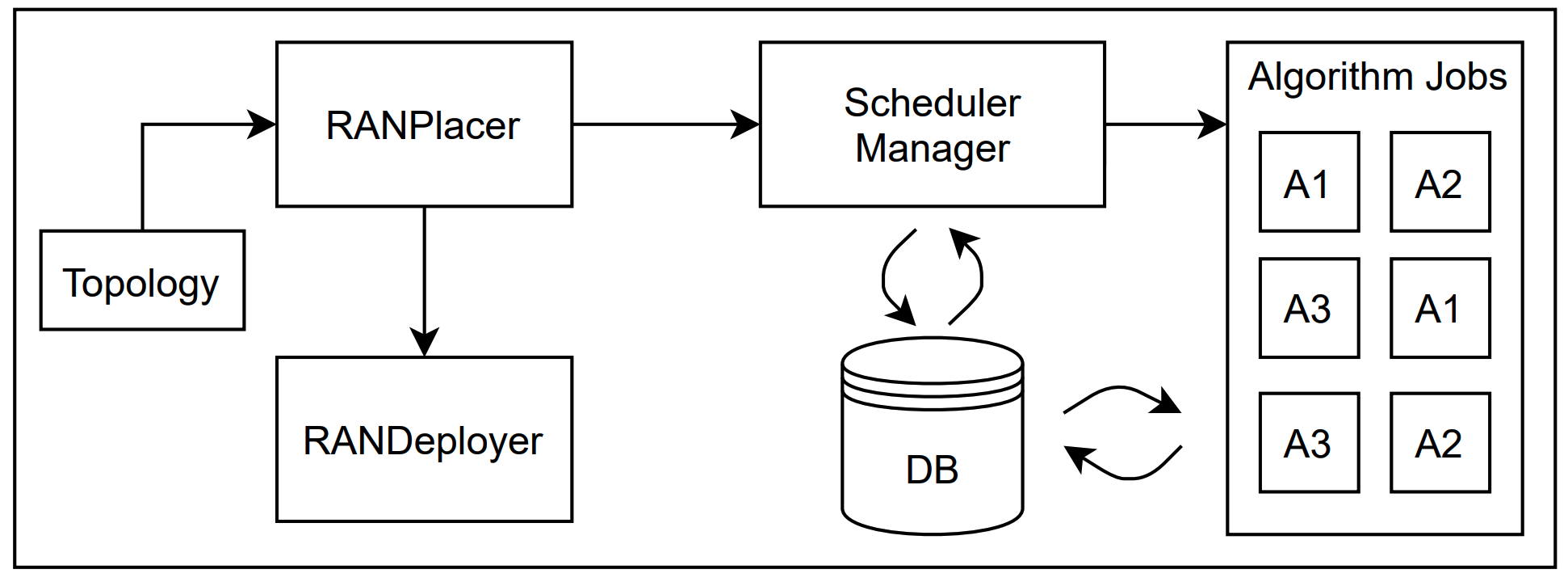
The RANPlacer architecture is composed of the following components:
- RANPlacer: Orchestrates the placement execution and the RANDeployer creation.
- RANDeployer: Manages the life cycle of the Virtual Network Functions (VNFs).
- Network Topology: Describes the network topology where the VNFs will be placed.
- Scheduler Manager: Manages the algorithm's executions.
- Algorithm Jobs: Execute the placement algorithms and store the results.
- Storage: Persistence layer that keeps the algorithm required information and results.
The RANPlacer is responsible for handling the placement requests triggered by the Network Operator (NO) input. It triggers the placement algorithm through the Scheduler API, provides the placement result once it is finished, and creates the required RANDeployer resources to start the VNFs in the selected nodes.
The RANPlacer receives the following arguments:
- RAN Topology name.
- RUs position.
- Placement Algorithm.
- Nodes information (Optional - if not provided will be calculated).
The RANDeployer is responsible for managing the life-cycle of a chain of VNFs. A chain is generally composed of a CU, DU, and RU that communicate with the Core Network (CN).
The RANDeployer creates all the required resources for VNFs execution and cleans up the environment once deleted.
The Scheduler Manager receives the requests from the RANPlacer with the inputs for the algorithm execution. The input is composed of the following information:
- Nodes Information: Contains the resources (CPU and Memory), node type (Core Network, Aggregation Layer), and links count.
- Network Topology: Description of the network, such as links and the link's capacity (bandwidth and latency).
- Algorithm: Defines the placement algorithm that should be used.
- RUs Position: Describes the number of RUs and where they should be placed.
The Scheduler Manager accepts HTTP POST and GET requests at the /scheduler endpoint.
Initially, a POST request with the inputs mentioned above should be executed. The server
will then asynchronously trigger the algorithm job execution and provide the RANPlacer
a token used to get the placement algorithm status and result through an
HTTP GET request.
In the future, more endpoints can be added, for example, to register a new algorithm, but
initially, only the scheduler endpoint will be available.
The algorithm jobs will be asynchronous tasks as they can take a considerable time to be finished. Also, queuing maybe consider in the future. According to the algorithm chosen by the network operator, a job will be triggered by the selected algorithm. Once the job finishes its execution, it will send the result to a persistency layer accessible by the Scheduler Manager.
The architecture is implemented on top of K8S, and for prototyping purposes, the persistence layer will take advantage of K8S config map resources, avoiding the complexity of managing a Database. It soon may be necessary to switch to a proper database.
