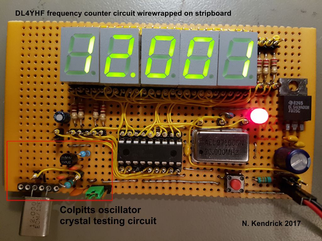
I have modified the code to support using an external crystal oscillator module on the PIC's OSC1/RA7/PB7 pin, which frees OSC2/RA6/PB6 as an output pin which can then be used to control display digit 5 instead of the diode/transistor NAND gate.
The original code and circuit schematics can be found here: http://www.qsl.net/dl4yhf/freq_counter/freq_counter.html
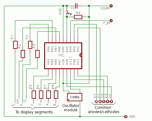
My modified circuit is:
With reference to the original schematic:
-
Omit C1, C2, X1, D1-4, R10 and T1 (The crystal oscillator circuit and the transistor/diode NAND gate that controls digit 5)
-
Connect the output of a (20MHz) TTL oscillator module to the OSC1 pin (16)
-
Connect OSC2/RA6/PB6 pin (15) to the common anode or cathode of display digit 5 (instead of using the transistor/diode NAND gate)
-
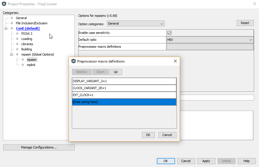
Compile the code, remembering to define appropriate values for:
-- DISPLAY_VARIANT_n - to match your circuit design (V1 or V2) and whether your display is common anode or cathode
-- CLOCK_VARIANT - to match your oscillator frequency
-- EXT_CLOCK - set to 1 if you are using an external oscillator module
Here's where to set these values in MPLAB X:
10-Sep-2017: I have tested this code on my stripboard build with a common ANODE display. I have also modified the code sections for common CATHODE displays, but have no current means to test it - if you use the code with such a display please let me know if anything needs changing.


