Hackathon: openOCT - Full-field Incoherent Interferemeter for better optical sectioning with remote control capabilities
Welcome to the openOCT Hackathon! In this hackathon, we will be addressing the crucial need for an open-source optical coherence tomography system that can help students learning more about setting up a low-coherence interferemoter. To keep the budget low, we aim for a full-field time domain OCT using an SLD (super luminescent diode) - alternatively one could also try an LED to lower the costs even more


Autofocus is a critical feature in microscopy as it helps to keep the sample in focus, resulting in high-quality imaging. Currently, there are software-based autofocus systems that maximize contrast based on the z-position of the sample or objective. However, hardware-based autofocus systems provide alternative solutions. These systems typically utilize a laser coupled into the detection path, reflecting off the sample (e.g., coverslip), and reaching a detector (e.g., quadrant diode, camera) via a beamsplitter. As the sample moves along the optical axis, the detected beam on the detector changes as a function of z, which can be processed using various techniques or electric circuits.
While some major microscope manufacturers offer hardware-based autofocus systems, they tend to be expensive. Software-based systems, on the other hand, are slow and lack real-time functionality. Although neural network-based systems show promise, they are not yet stable enough. Thus, there is a clear need for an open-source hardware-based autofocus system that is affordable, precise, and accessible to anyone.
For further reading on the topic, we recommend the review article "Advances in Hardware Autofocus Systems for Microscopy" available at: Link to Article
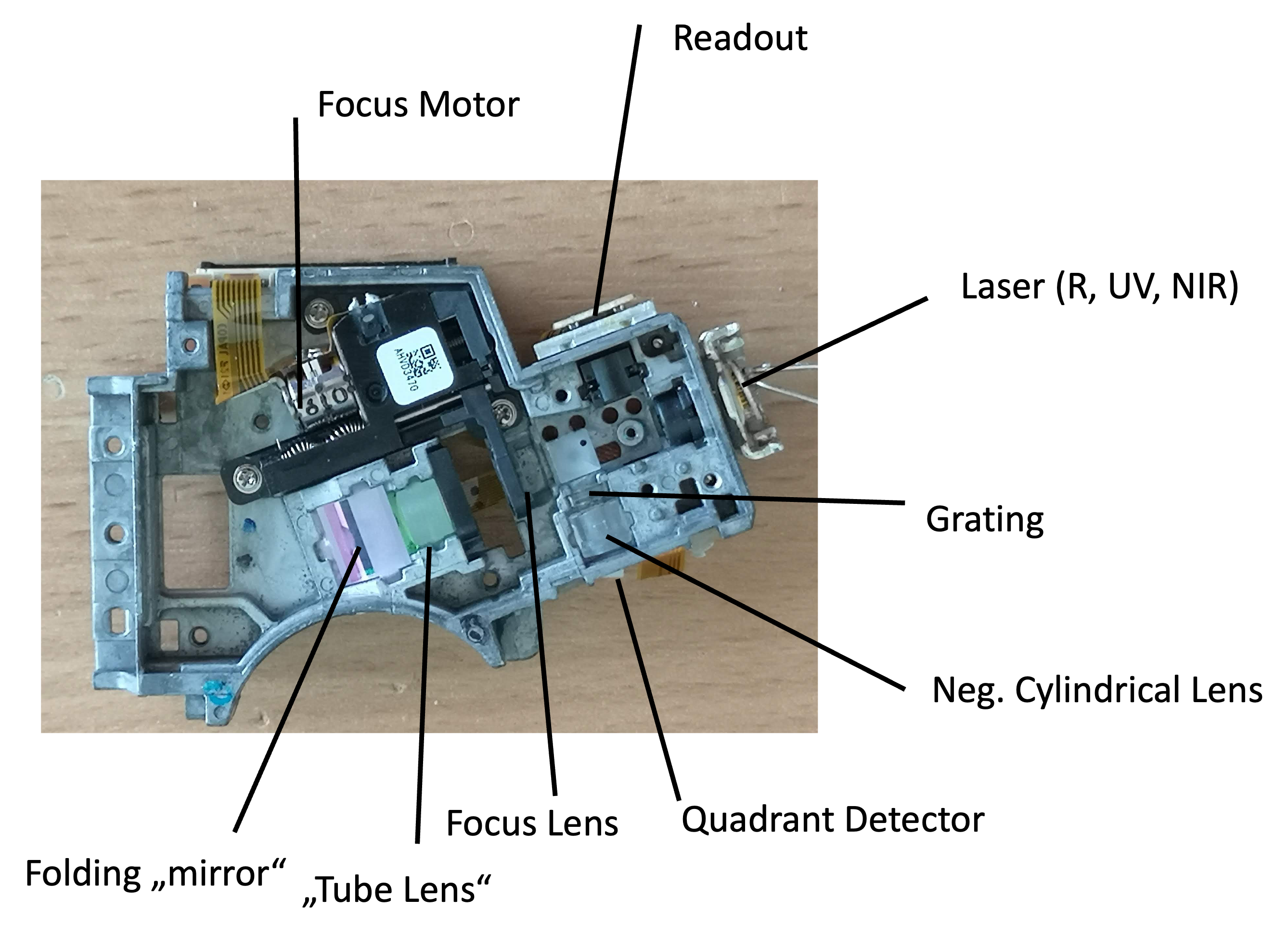
The primary objective of this hackathon is to build an affordable hardware module for autofocus using readily available components, namely the optical pickup unit (OPU) from a PS3 Bluray drive and the SEEED XIAO ESP32-S3 Camera. The PS3 OPU employs an astigmatism-based autofocus technique, which maintains a constant distance between the disk and the detection lens. To replicate this functionality, we will replace the quadrant diode with a camera and utilize image processing algorithms, either on the ESP32 microcontroller or in Python, to compute the astigmatism as a function of the focus along the z-axis.
Ultimately, the goal is to create a hardware module capable of continuously tracking the focus and providing a signal to a motor, ensuring that the focus remains constant during microscopy experiments.
The use of optical pickup units (OPUs) from Bluray/HD-DVD players has been extensively explored in various applications, including force measurements, atomic force microscopy, nanoprinting, and laser scanning microscopy. These OPUs are highly integrated photonic devices with immense potential. If you're interested in delving deeper into OPU hacking, there are informative forum discussions available at: Link to Forum
To gain a comprehensive understanding, we recommend watching this enlightening video: Link to Video
For a concise summary of OPU hacking, you can refer to this document: Link to Summary
OPUs are widely available in large quantities as discarded electronic components, making them an ideal resource for hacking and repurposing.
The SEEED XIAO ESP32-S3 Camera, integrated with the ESP32 microcontroller, provides a convenient solution for streaming images over USB or Wi-Fi. Also, the microcontroller has enough power to do basic image processing such as gaussian bluring, min/max estimation, etc. Enough to evtl. do the focus computation on the device before transmitting the information to e.g. a computer.
At present, we have a functional prototype that combines the SEEED XIAO ESP32-S3 camera (OV2640 chip) with the PS3 OPU (KES400A) for the autofocus system. During the prototyping phase, we utilize a red diode (650nm) instead of UV (405nm) or IR (850nm) to facilitate beam visibility. However, using NIR (near-infrared) diodes would be more suitable for fluorescence excitation and maintaining invisibility.
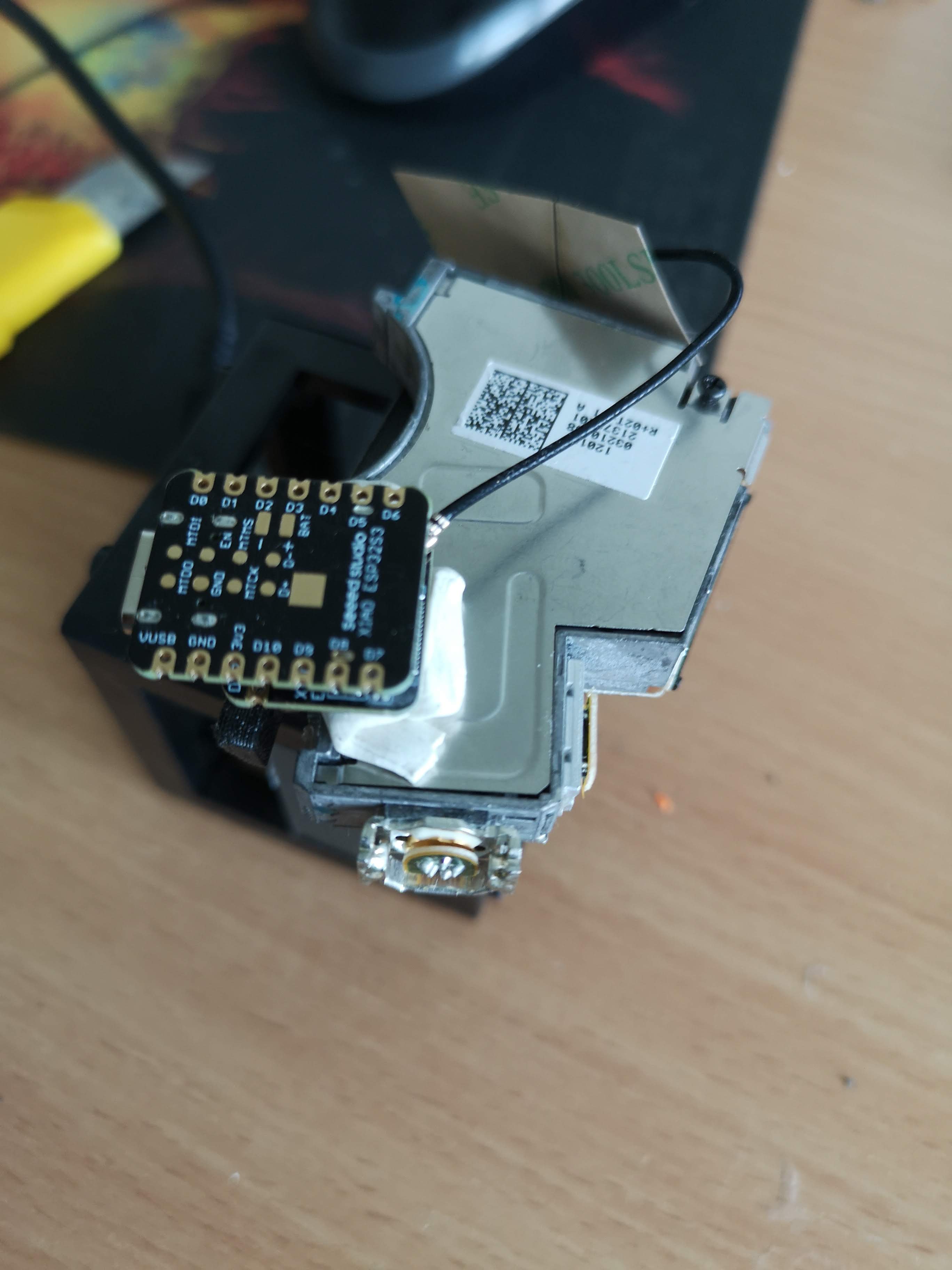
To modify the OPU, we remove the focusing lens and quadrant diode. In place of the quadrant diode, we position the camera without its lens to detect the astigmatism. This assembly is attached to a microscope objective lens, and a simple coverslip serves as a beamsplitter. The beam from the OPU to the objective lens' back focal plane (BFP) is collimated. Ideally, the camera should be confocal with the sample plane. The entire assembly takes the form of a cube, with the mirror adjustable to ensure it hits the BFP in the center and remains parallel to the optical axis.
To protect the camera (or flatband cable) from immediate damage, we use a camera with a long cable.
The simplest prototype involves replacing the diode with the camera and substituting the read-out lens with the objective lens.
All design files are available in the INVENTOR folder
All 3D printing files are available in the STL folder
Setup from bottom view: 3 (ball-loaded) set screws in combination with 2 pulling springs allow the beamsplitter (18x18mm^2 coverslip) to be adjusted w.r.t. the BFP of the objective lens

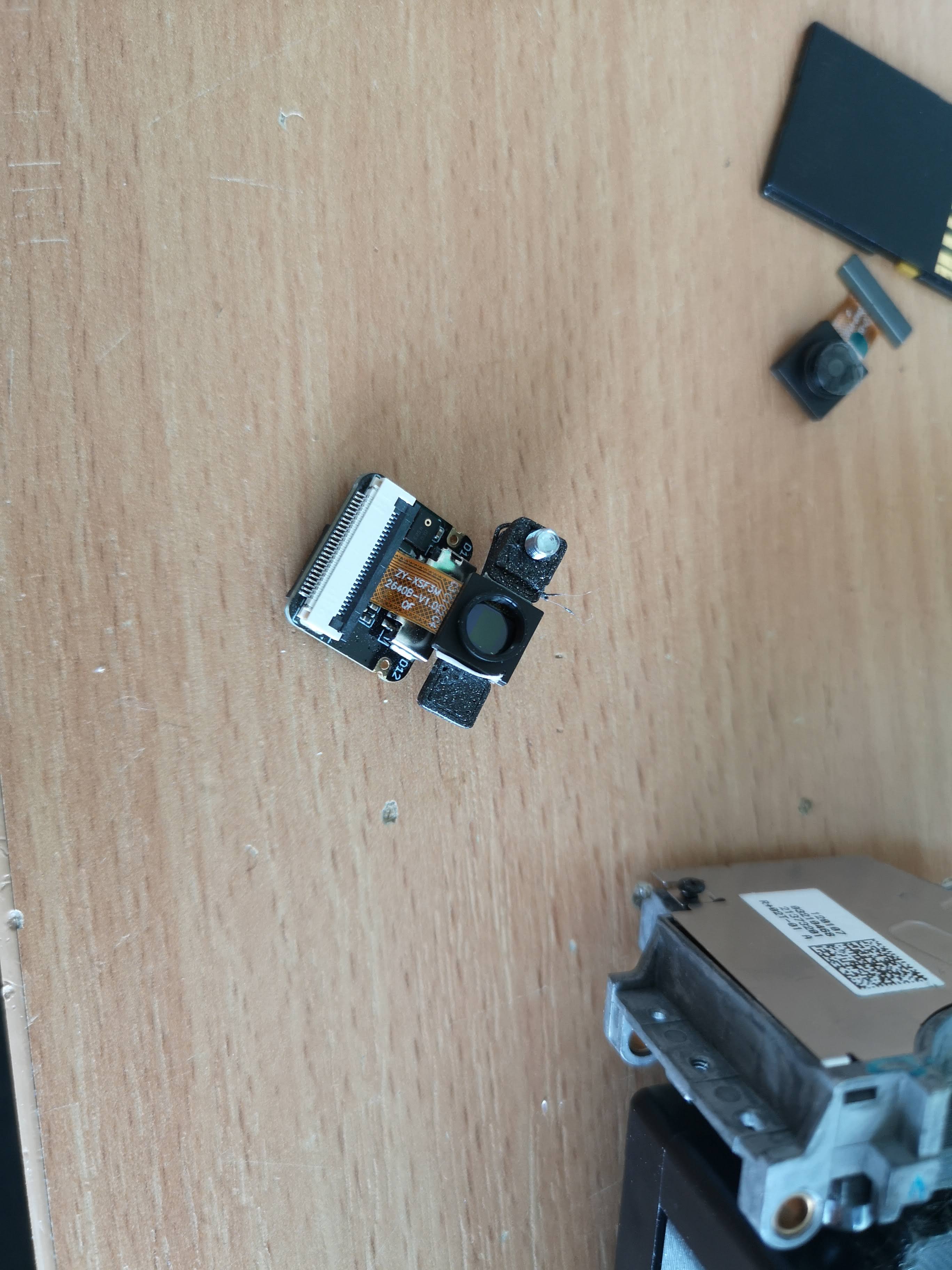
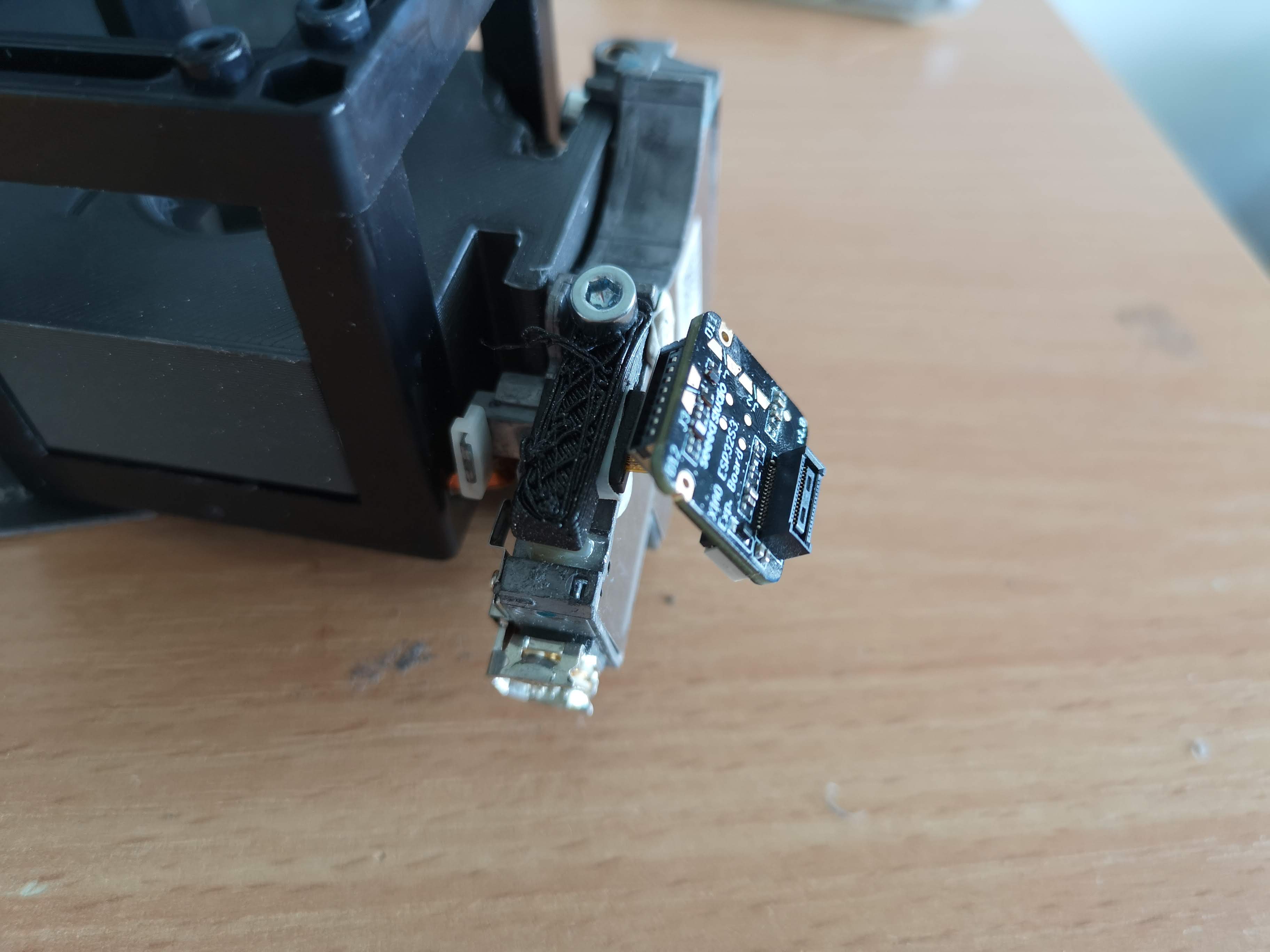
The XIAO camera is mounted in place of the quadrant diode (A holding mechanism is missing)

The camera comes under an angle since the cylindrical lens is not perpendicular to the pixels otherwise:

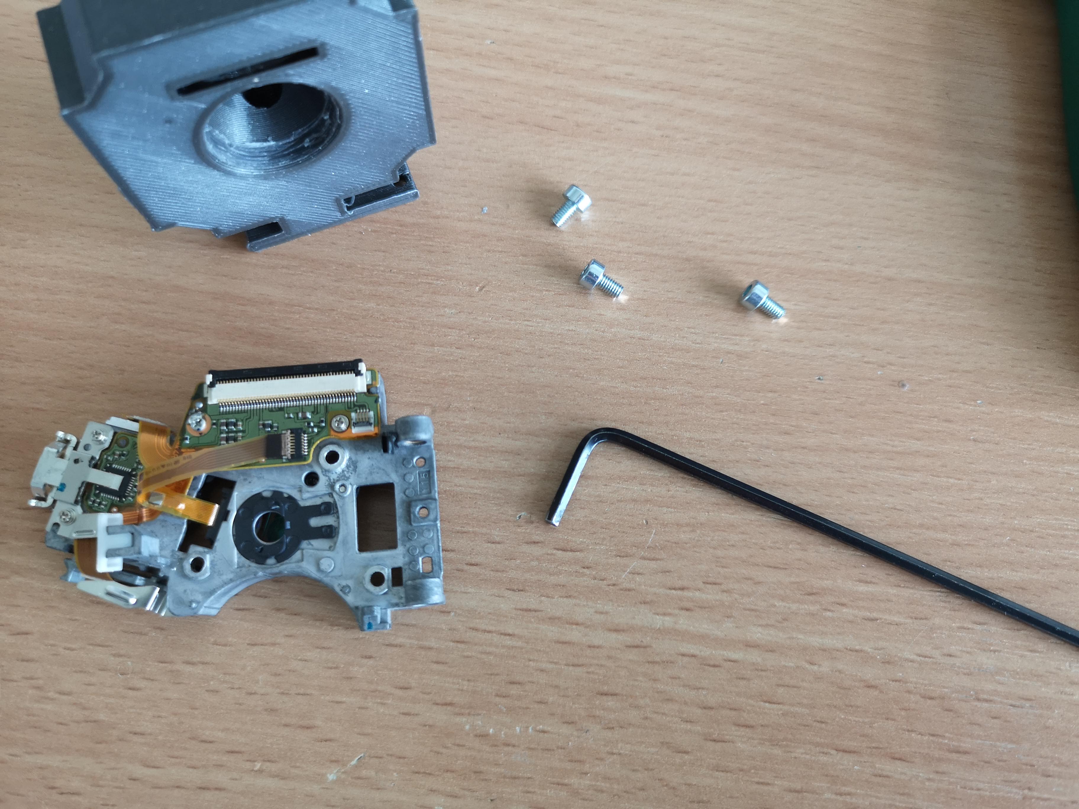
To disassemble the OPU, you can remove the metal plate at the back and the detection lens using Philips screwdrivers.
The back of the OPU features a complex and precisely adjusted "confocal" microscope:
To attach this unit to a 3D printed assembly, we will enlarge the holes where the lens used to be, making them M3-sized, and then incorporate the assembly into a UC2 insert:
The Xiao camera module can be adapted using another 3D printed mechanism (customizable to your needs). It's worth noting that the astigmatism is not parallel to the case of the OPU, so it may be necessary to adjust the angle by rotating the camera. Additionally, the focus may be slightly closer than the plastic cap (black) of the camera module allows.
We create an initial prototype as follows:
It is advisable to mount the XIAO camera securely to prevent damage to the flatband cable:
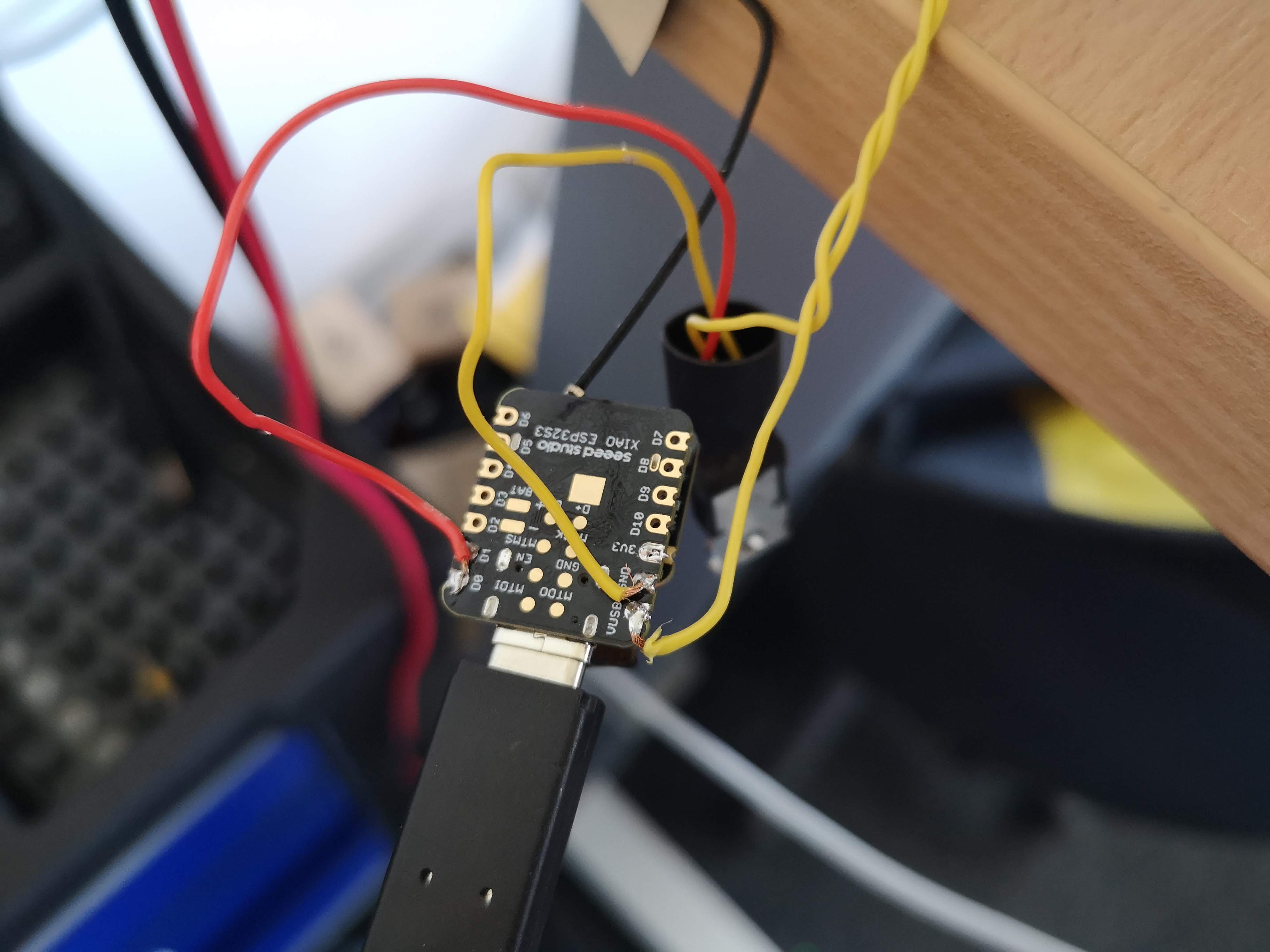
The laser diode can be directly powered by the 3V3 supply voltage or controlled using a transistor for on/off switching in the code.
Fully assembled
The optical setup for the autofocus system involves several components and configurations. Here is an overview of the setup:
- Laser Collimation: The laser beam is roughly collimated using a lens that also features a grating. The purpose of the grating is yet to be determined.
- Spatial Light Modulator (SLM): The laser beam passes through a tiny SLM, which shapes the beam according to specific requirements.
- Polarizing Beam Splitters: The shaped beam is directed through two polarizing beam splitters before it is steered towards the objective lens.
- Polarization Rotation: The reflected light from the sample undergoes polarization rotation using a quarter-wave plate.
- Detection: The polarizing beam splitter reflects the light towards the detector. Between the beamsplitter and the detector, a small grating is positioned along with a negative cylindrical lens.
- Grating and Negative Cylindrical Lens: The combination of the grating and negative cylindrical lens plays a crucial role in the autofocus system:
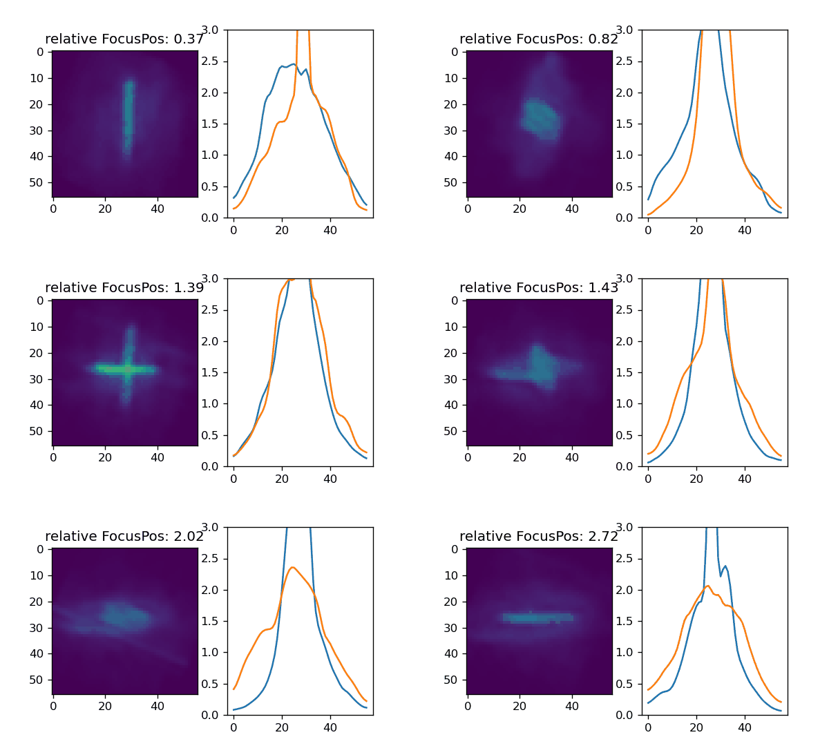
- A collimated beam results in a cross or the best-focused image on the detector.
- An out-of-focus beam leads to a line structure along the x or y axis, depending on whether it is positively or negatively out of focus.
- Typically, a quadrant detector is used to measure the differences between the sums of intensities (A-B)+(C-D).
- The resulting S-curve can be used for absolute or relative focus tracking in a linear regime.
- The S-curve switches signs at the outer regions because the astigmatism rotates as a function of atan2.
The practical implementation of this setup may look like the following animation:
The combination of these optical elements allows for precise detection and tracking of focus in the autofocus system.
The general code is divided into two pieces:
- cpp code that can be used in the aRduino IDE or better Platform.io in Visual studio code that reads out the camera, sets up expsoure and gain and converts the data to a byte stream to send it out via Serial
- python code to send data (E.g. request frame, setup camera parameter), receive the data and converts it to numpy arrays
The code is copied from our matchboxscope repository: https://github.com/Matchboxscope/matchboxscope-simplecamera/tree/autofocus
#include "esp_camera.h"
#include <base64.h>

#define BAUD_RATE 2000000

#define PWDN_GPIO_NUM -1
#define RESET_GPIO_NUM -1
#define XCLK_GPIO_NUM 10
#define SIOD_GPIO_NUM 40
#define SIOC_GPIO_NUM 39

#define Y9_GPIO_NUM 48
#define Y8_GPIO_NUM 11
#define Y7_GPIO_NUM 12
#define Y6_GPIO_NUM 14
#define Y5_GPIO_NUM 16
#define Y4_GPIO_NUM 18
#define Y3_GPIO_NUM 17
#define Y2_GPIO_NUM 15
#define VSYNC_GPIO_NUM 38
#define HREF_GPIO_NUM 47
#define PCLK_GPIO_NUM 13

#define LED_GPIO_NUM 21

void grabImage();
void cameraInit();

void setup()
{
  Serial.begin(BAUD_RATE);
  Serial.setTimeout(20);
  cameraInit();
}

int Nx = 320;
int Ny = 240;
int Nroi = 50;
int x = 320 / 2;
int y = 240 / 2;
bool isStreaming = true;

/* setting expsorue time: t1000
setting gain: g1
getting frame: \n
restarting: r0 */
void loop()
{
  // Check for incoming serial commands
  if (Serial.available() > 0)
  {
    String command = Serial.readString(); // Read the command until a newline character is received
    if (command.length() > 1 && command.charAt(0) == 't')
    {
      // exposure time
      int value = command.substring(1).toInt(); // Extract the numeric part of the command and convert it to an integer
      // Use the value as needed
      // Apply manual settings for the camera
      sensor_t *s = esp_camera_sensor_get();
      s->set_gain_ctrl(s, 0);     // auto gain off (1 or 0)
      s->set_exposure_ctrl(s, 0); // auto exposure off (1 or 0)
      s->set_aec_value(s, value); // set exposure manually (0-1200)
    }
    else if (command.length() > 1 && command.charAt(0) == 'g')
    {
      // gain
      int value = command.substring(1).toInt(); // Extract the numeric part of the command and convert it to an integer

      // Apply manual settings for the camera
      sensor_t *s = esp_camera_sensor_get();
      s->set_gain_ctrl(s, 0);     // auto gain off (1 or 0)
      s->set_exposure_ctrl(s, 0); // auto exposure off (1 or 0)
      s->set_agc_gain(s, value);  // set gain manually (0 - 30)
    }
    else if (command.length() > 1 && command.charAt(0) == 'r')
    {
      // restart
      ESP.restart();
    }
    else
    {
      // capture image and return
      grabImage();
    }

    // flush serial
    while (Serial.available() > 0)
    {
      char c = Serial.read();
    }
  }
}

void cameraInit()
{

  camera_config_t config;
  config.ledc_channel = LEDC_CHANNEL_0;
  config.ledc_timer = LEDC_TIMER_0;
  config.pin_d0 = Y2_GPIO_NUM;
  config.pin_d1 = Y3_GPIO_NUM;
  config.pin_d2 = Y4_GPIO_NUM;
  config.pin_d3 = Y5_GPIO_NUM;
  config.pin_d4 = Y6_GPIO_NUM;
  config.pin_d5 = Y7_GPIO_NUM;
  config.pin_d6 = Y8_GPIO_NUM;
  config.pin_d7 = Y9_GPIO_NUM;
  config.pin_xclk = XCLK_GPIO_NUM;
  config.pin_pclk = PCLK_GPIO_NUM;
  config.pin_vsync = VSYNC_GPIO_NUM;
  config.pin_href = HREF_GPIO_NUM;
  config.pin_sscb_sda = SIOD_GPIO_NUM;
  config.pin_sscb_scl = SIOC_GPIO_NUM;
  config.pin_pwdn = PWDN_GPIO_NUM;
  config.pin_reset = RESET_GPIO_NUM;
  config.xclk_freq_hz = 20000000;
  // config.frame_size = FRAMESIZE_QVGA;
  // config.pixel_format = PIXFORMAT_JPEG; // for streaming
  // config.pixel_format = PIXFORMAT_RGB565; // for face detection/recognition
  config.grab_mode = CAMERA_GRAB_WHEN_EMPTY;
  config.fb_location = CAMERA_FB_IN_PSRAM;
  config.jpeg_quality = 12;

  config.pixel_format = PIXFORMAT_JPEG;
  config.frame_size = FRAMESIZE_QVGA; // for streaming}

  config.fb_count = 1;

  esp_err_t err = esp_camera_init(&config);
  if (err != ESP_OK)
  {
    return;
  }

  sensor_t *s = esp_camera_sensor_get();
  s->set_hmirror(s, 1);
  s->set_vflip(s, 1);

  // enable manual camera settings
  s->set_gain_ctrl(s, 0);     // auto gain off (1 or 0)
  s->set_exposure_ctrl(s, 0); // auto exposure off (1 or 0)
  s->set_aec_value(s, 100);   // set exposure manually (0-1200)
  s->set_agc_gain(s, 0);      // set gain manually (0 - 30)
}
void grabImage()
{

  camera_fb_t *fb = esp_camera_fb_get();

  if (!fb || fb->format != PIXFORMAT_JPEG)
  {
    Serial.println("Failed to capture image");
    ESP32.restart();
  }
  else
  {
    delay(40);

    String encoded = base64::encode(fb->buf, fb->len);
    Serial.write(encoded.c_str(), encoded.length());
    Serial.println();
  }

  esp_camera_fb_return(fb);
}import time
from threading import Thread
import numpy as np
import serial.tools.list_ports
import base64
from PIL import Image
import io
class CameraESP32CamSerial:
def __init__(self):
super().__init__()
self.__logger = initLogger(self, tryInheritParent=True)
# many to be purged
self.model = "ESP32Camera"
self.shape = (0, 0)
self.isConnected = False
# camera parameters
self.framesize = 100
self.exposure_time = 0
self.analog_gain = 0
self.SensorWidth = 320
self.SensorHeight = 240
self.manufacturer = 'Espressif'
self.frame = np.ones((self.SensorHeight,self.SensorWidth))
self.isRunning = False
# string to send data to camera
self.newCommand = ""
self.exposureTime = -1
self.gain = -1
self.serialdevice = self.connect_to_usb_device()
def connect_to_usb_device(self):
ports = serial.tools.list_ports.comports()
for port in ports:
if port.manufacturer == self.manufacturer or port.manufacturer=="Microsoft":
try:
ser = serial.Serial(port.device, baudrate=2000000, timeout=1)
print(f"Connected to device: {port.description}")
return ser
except serial.SerialException:
print(f"Failed to connect to device: {port.description}")
print("No matching USB device found.")
return None
def put_frame(self, frame):
self.frame = frame
return frame
def start_live(self):
self.isRunning = True
self.mThread = Thread(target=self.startStreamingThread)
self.mThread.start()
def stop_live(self):
self.isRunning = False
self.mThread.join()
try:self.serialdevice.close()
except:pass
def suspend_live(self):
self.isRunning = False
def prepare_live(self):
pass
def close(self):
try:self.serialdevice.close()
except:pass
def setPropertyValue(self, property_name, property_value):
# Check if the property exists.
if property_name == "gain":
self.set_analog_gain(property_value)
elif property_name == "exposure":
self.set_exposure_time(property_value)
else:
self.__logger.warning(f'Property {property_name} does not exist')
return False
return property_value
def getPropertyValue(self, property_name):
# Check if the property exists.
if property_name == "gain":
property_value = self.gain
elif property_name == "exposure":
property_value = self.exposureTime
else:
self.__logger.warning(f'Property {property_name} does not exist')
return False
return property_value
def set_exposure_time(self, exposureTime):
self.newCommand = "t"+str(exposureTime)
self.exposureTime = exposureTime
def set_analog_gain(self, gain):
self.newCommand = "g"+str(gain)
self.gain = gain
def getLast(self):
return self.frame
def startStreamingThread(self):
# if we have never connected anything we should return and not always try to reconnecnt
if self.serialdevice is None:
return
nFrame = 0
nTrial = 0
while self.isRunning:
try:
# send new comamand to change camera settings, reset command
if not self.newCommand == "":
self.serialdevice.write((self.newCommand+' \n').encode())
self.newCommand = ""
# request new image
self.serialdevice.write((' \n').encode())
# don't read to early
time.sleep(.05)
# readline of camera
imageB64 = self.serialdevice.readline()
# decode byte stream
image = np.array(Image.open(io.BytesIO(base64.b64decode(imageB64.decode()))))
self.frame = np.mean(image,-1)
nFrame += 1
except Exception as e:
# try to reconnect
#print(e) # most of the time "incorrect padding of the bytes "
nFrame = 0
nTrial+=1
try:
self.serialdevice.flushInput()
self.serialdevice.flushOutput()
except:
pass
if nTrial > 10 and type(e)==serial.serialutil.SerialException:
try:
# close the device - similar to hard reset
self.serialdevice.setDTR(False)
self.serialdevice.setRTS(True)
time.sleep(.1)
self.serialdevice.setDTR(False)
self.serialdevice.setRTS(False)
time.sleep(.5)
#self.serialdevice.close()
except: pass
self.serialdevice = self.connect_to_usb_device()
nTrial = 0
def getLastChunk(self):
return self.frame
def setROI(self, hpos, vpos, hsize, vsize):
return #hsize = max(hsize, 256) # minimum ROIMore scripts can be found here: https://github.com/Matchboxscope/matchboxscope-simplecamera/tree/autofocus/PYTHON
A test stack for the astimatism can be found here: https://github.com/Matchboxscope/matchboxscope-simplecamera/raw/autofocus/PYTHON/realAstigmatismStack.tif
We want to be able to use this as an online-running autofocus in ImSwitch. Relevant code passages are the camera interface for the herein created USB-serial camera:
The FocusLockController
- have one working system
- Detect the focus as one number from the astimatism as a function of the z-position
- have a controller that may give step-values for the focus motor
- have a functioning focuscontroller inside imswitch that can keep the focus
