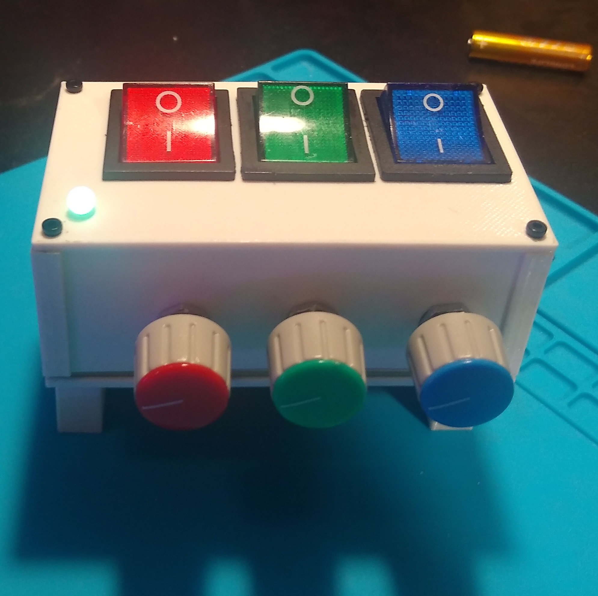
A simple project demonstrating how an RGB LED works. By adjusting potentiometers, users can mix red, green, and blue light to create any color in the RGB spectrum.
- Overview
- Features
- Hardware Components
- Enclosure Design
- Getting Started
- Assembly Instructions
- Usage
- Contributing
- License
- Acknowledgments
This project consists of a PCB board designed in KiCad and an enclosure designed in OpenSCAD, which can be 3D printed. The circuit allows users to adjust the intensity of red, green, and blue channels of an RGB LED using potentiometers, creating a full range of colors.
- RGB Color Mixing: Adjust potentiometers to mix red, green, and blue light.
- Custom PCB Design: PCB board designed using KiCad.
- 3D Printable Enclosure: Box designed in OpenSCAD for housing the PCB and components.
- Electronics:
- 1 x Common Cathode RGB LED
- 3 x Potentiometers (e.g., 10kΩ linear taper)
- 3 x Current-limiting resistors for the RGB LED (calculate based on your LED specs)
- 3 x Rocker switches
- 1 x PCB (design files included)
- 3 x AAA battery
- Wires and connectors as needed
- Some M2 screws
- Tools Required:
- Soldering iron and solder
- Wire cutters/strippers
- Multimeter (optional for testing)
Components examples:
The enclosure is designed in OpenSCAD and can be 3D printed. The design files are available in the openscad_src directory. Ensure your 3D printer is calibrated correctly for precise fitting of components.
- Clone the Repository: Clone this repository to your local machine using
git clone https://github.com/KubaTaba1uga/electronics_rgb_led_toy.git. - Review the Schematics: Open the KiCad files located in the
kicad_srcdirectory to understand the circuit design. - Prepare the PCB: Manufacture the PCB using the provided design files or use a prototyping board for initial testing.
- Gather Components: Ensure all necessary components are available before assembly.
- Solder Components: Solder the RGB LED, potentiometers, resistors, and connectors onto the PCB as per the schematic.
- Assemble Enclosure: 3D print the enclosure and place the assembled PCB inside, securing it appropriately.
- Adjust Colors: Rotate the potentiometers to vary the intensity of each color channel (red, green, blue) and observe the resulting color from the RGB LED.
- Experiment: Mix different levels to create various colors and understand additive color mixing principles.
Contributions are welcome! Please fork the repository and create a pull request with your proposed changes. Ensure your code adheres to the project's coding standards and includes appropriate documentation.
This project is licensed under the MIT License. See the LICENSE file for more details.
