| permalink |
|---|
index.html |
Hi, I'm Fomu! This workshop covers the basics of Fomu in a top-down approach. We'll start out by learning what Fomu is, how to load software into Fomu, and finally how to write software for Fomu.
FPGAs are complex, weird things, so we'll take a gentle approach and start out by treating it like a Python interpreter first, and gradually peel away layers until we're writing our own hardware registers. You can take a break at any time and explore! Stop when you feel the concepts are too unfamiliar, or plough on and dig deep into the world of hardware.
- TOC {:toc}
For this workshop, you will need a Fomu board. This workshop may be competed with any model of Fomu, though there are some parts that require you to identify which model you have:
| Hacker | Production | |
|---|---|---|
| String | hacker | pvt |
| Bash Command | export FOMU_REV=hacker |
export FOMU_REV=pvt |
| Front | 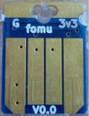 |
 |
| Back | 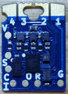 |
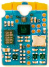 |
| In Case | 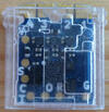 |
 |
| Partse | 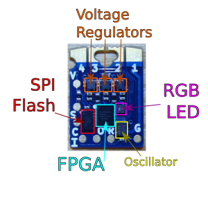 |
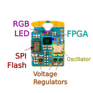 |
| Color | dark blue | cyan / light blue |
| Bootloader | Fomu Hacker running DFU Bootloader vX.X.X | Fomu PVT running DFU Bootloader vX.X.X |
| Description | These are the original design and cut corners to make it easier to manufacture. If you received one directly from Tim before 36C3, you probably have one of these. Hacker boards have white silkscreen on the back. | If you ordered a Fomu from Crowd Supply, this is the model you'll receive. It is small, and fits in a USB port. There is no silkscreen on it. This model of Fomu has a large silver crystal oscillator that is the tallest component on the board. |
| Received at | From Tim at 35C3, CCCamp19, HackADay Supercon 2019 | At RISC-V Summit 2019, 36C3, Crowdsupply, Mouser |
| Buy more | End of Life | CrowdSupply, Mouser |
Your Fomu should be running Foboot v1.8.7 or newer. You can see what version you are running by typing dfu-util -l and noting the version number.
Aside from that, you need a computer with a USB port that can run the toolchain software. You should not need any special drivers, though on Linux you may need sudo access, or special udev rules to grant permission to use the USB device from a non-privileged account.
There are also Fomu EVT boards which were shipped to early backers of the Fomu crowd funding campaign. This model of Fomu is about the size of a credit card. It should have the text "Fomu EVT3" written across it in white silkscreen. If you have a different EVT board such as EVT2 or EVT1, they should work also.
You will need the Workshop files. They are located in the fomu-workshop Github repository. You can download master.zip or clone it from git:
git clone --recurse-submodules https://github.com/im-tomu/fomu-workshop.git
If you're attending a workshop that provides USB drives, these files may be available on the USB drive under the Workshop directory.
Fomu requires specialized software. This software is provided for Linux x86/64, macOS, and Windows, via Fomu Toolchain.
Debian packages are also available for Raspberry Pi.
If you're taking this workshop as a class, the toolchains are provided on the USB disk.
To install the software, extract it somewhere on your computer, then open up a terminal window and add that directory to your PATH:
- macOS:
export PATH=[path-to-toolchain]/bin:$PATH - Linux:
export PATH=[path-to-toolchain]/bin:$PATH - Windows Powershell:
$ENV:PATH = "[path-to-toolchain]\bin;" + $ENV:PATH - Windows cmd.exe:
PATH=[path-to-toolchain]\bin;%PATH%
To confirm installation, run the yosys command and confirm you get the following output;
$ yosys

 /----------------------------------------------------------------------------\
 |                                                                            |
 |  yosys -- Yosys Open SYnthesis Suite                                       |
 |                                                                            |
 |  Copyright (C) 2012 - 2018  Clifford Wolf <[email protected]>           |
 |                                                                            |
 |  Permission to use, copy, modify, and/or distribute this software for any  |
 |  purpose with or without fee is hereby granted, provided that the above    |
 |  copyright notice and this permission notice appear in all copies.         |
 |                                                                            |
 |  THE SOFTWARE IS PROVIDED "AS IS" AND THE AUTHOR DISCLAIMS ALL WARRANTIES  |
 |  WITH REGARD TO THIS SOFTWARE INCLUDING ALL IMPLIED WARRANTIES OF          |
 |  MERCHANTABILITY AND FITNESS. IN NO EVENT SHALL THE AUTHOR BE LIABLE FOR   |
 |  ANY SPECIAL, DIRECT, INDIRECT, OR CONSEQUENTIAL DAMAGES OR ANY DAMAGES    |
 |  WHATSOEVER RESULTING FROM LOSS OF USE, DATA OR PROFITS, WHETHER IN AN     |
 |  ACTION OF CONTRACT, NEGLIGENCE OR OTHER TORTIOUS ACTION, ARISING OUT OF   |
 |  OR IN CONNECTION WITH THE USE OR PERFORMANCE OF THIS SOFTWARE.            |
 |                                                                            |
 \----------------------------------------------------------------------------/

 Yosys 78b30bbb1102047585d1a2eac89b1c7f5ca7344e (Fomu build) (git sha1 41d9173, gcc 5.5.0-12ubuntu1~14.04 -fPIC -Os)


yosys>
Ensure it says (Fomu build). Type exit to quit yosys.
The Fomu Toolchain consists of the following tools;
Tool Purpose yosys Verilog synthesis nextpnr-ice40 FPGA place-and-route icestorm FPGA bitstream packing riscv toolchain Compile code for a RISC-V softcore dfu-util Load a bitstream or code onto Fomu python Convert Migen/Litex code to Verilog wishbone-tool Interact with Fomu over USB serial console Interact with Python over a virtual console
Field Programmable Gate Arrays (FPGAs) are arrays of gates that are programmable in the field. Unlike most chips you will encounter, which have transistor gates arranged in a fixed order, FPGAs can change their configuration by simply loading new code. Fundamentally, this code programs lookup tables which form the basic building blocks of logic.
These lookup tables (called LUTs) are so important to the design of an FPGA that they usually form part of the name of the part. For example, Fomu uses a UP5K, which has about 5000 LUTs. NeTV used an LX9, which had about 9000 LUTs, and NeTV2 uses a XC7A35T that has about 35000 LUTs.
This is the SB_LUT4, which is the basic building block of Fomu. It has four inputs and one output. To program Fomu, we must define what each possible input pattern will create on the output.
To do this, we turn to a truth table:
| 0 | 1 | 2 | 3 | 4 | 5 | 6 | 7 | 8 | 9 | 10 | 11 | 12 | 13 | 14 | 15 | |
|---|---|---|---|---|---|---|---|---|---|---|---|---|---|---|---|---|
| IO0 | 0 | 0 | 0 | 0 | 0 | 0 | 0 | 0 | 1 | 1 | 1 | 1 | 1 | 1 | 1 | 1 |
| IO1 | 0 | 0 | 0 | 0 | 1 | 1 | 1 | 1 | 0 | 0 | 0 | 0 | 1 | 1 | 1 | 1 |
| IO2 | 0 | 0 | 1 | 1 | 0 | 0 | 1 | 1 | 0 | 0 | 1 | 1 | 0 | 0 | 1 | 1 |
| IO3 | 0 | 1 | 0 | 1 | 0 | 1 | 0 | 1 | 0 | 1 | 0 | 1 | 0 | 1 | 0 | 1 |
| O | ? | ? | ? | ? | ? | ? | ? | ? | ? | ? | ? | ? | ? | ? | ? | ? |
For example, to create a LUT that acted as an AND gate, we would define O to be 0 for everything except the last column. To create a NAND gate, we would define O to be 1 for everything except the last column.
FPGA LUTs are almost always n-inputs to 1-output. The ICE family of FPGAs from Lattice have 4-input LUTs. Xilinx parts tend to have 5- or 6-input LUTs which generally means they can do more logic in fewer LUTs. Comparing LUT count between FPGAs is a bit like comparing clock speed between different CPUs - not entirely accurate, but certainly a helpful rule of thumb.
It is from this simple primitive that we build up the building blocks of FPGA design.
Writing lookup tables is hard, so people have come up with abstract Hardware Description Languages (HDLs) we can use to describe them. The two most common languages are Verilog and VHDL. In the open source world, Verilog is more common. However, a modern trend is to embed an HDL inside an existing programming language, such as how Migen is embedded in Python, or SpinalHDL is embedded in Scala.
Here is an example of a Verilog module:
module example (output reg [0:5] Q, input C);
	reg [0:8] counter;
	always @(posedge C)
	begin
		counter <= counter + 1'b1;
		Q = counter[3] ^ counter[5] | counter<<2;
	end
endmodule
We can run this Verilog module through a synthesizer to turn it into SB_LUT4 blocks, or we can turn it into a more familiar logic diagram:
If we do decide to synthesize to SB_LUT4 blocks, we will end up with a pile of LUTs that need to be strung together somehow. This is done by a Place-and-Route tool. This performs the job of assigning physical LUTs to each LUT that gets defined by the synthesizer, and then figuring out how to wire it all up.
Once the place-and-route tool is done, it generates an abstract file that needs to be translated into a format that the hardware can recognize. This is done by a bitstream packing tool. Finally, this bitstream needs to be loaded onto the device somehow, either off of a SPI flash or by manually programming it by toggling wires.
We will use an ICE40UP5K for this workshop. This chip has a number of very nice features:
- 5280 4-input LUTs (LC)
- 16 kilobytes BRAM
- 128 kilobytes "SPRAM"
- Current-limited 3-channel LED driver
- 2x I2C and 2x SPI
- 8 16-bit DSP units
- Warmboot capability
- Open toolchain
Many FPGAs have what's called block RAM, or BRAM. This is frequently used to store data such as buffers, CPU register files, and large arrays of data. This type of memory is frequently reused as RAM on many FPGAs. The ICE40UP5K is unusual in that it also as 128 kilobytes of Single Ported RAM that can be used as memory for a softcore (a term used for a CPU core running inside an FPGA, to differentiate it from a 'hard' - i.e. fixed chip - implementation). That means that, unlike other FPGAs, valuable block RAM isn't taken up by system memory.
Additionally, the ICE40 family of devices generally supports "warmboot" capability. This enables us to have multiple designs live on the same FPGA and tell the FPGA to swap between them.
As always, this workshop wouldn't be nearly as easy without the open toolchain that enables us to port it to a lot of different platforms.
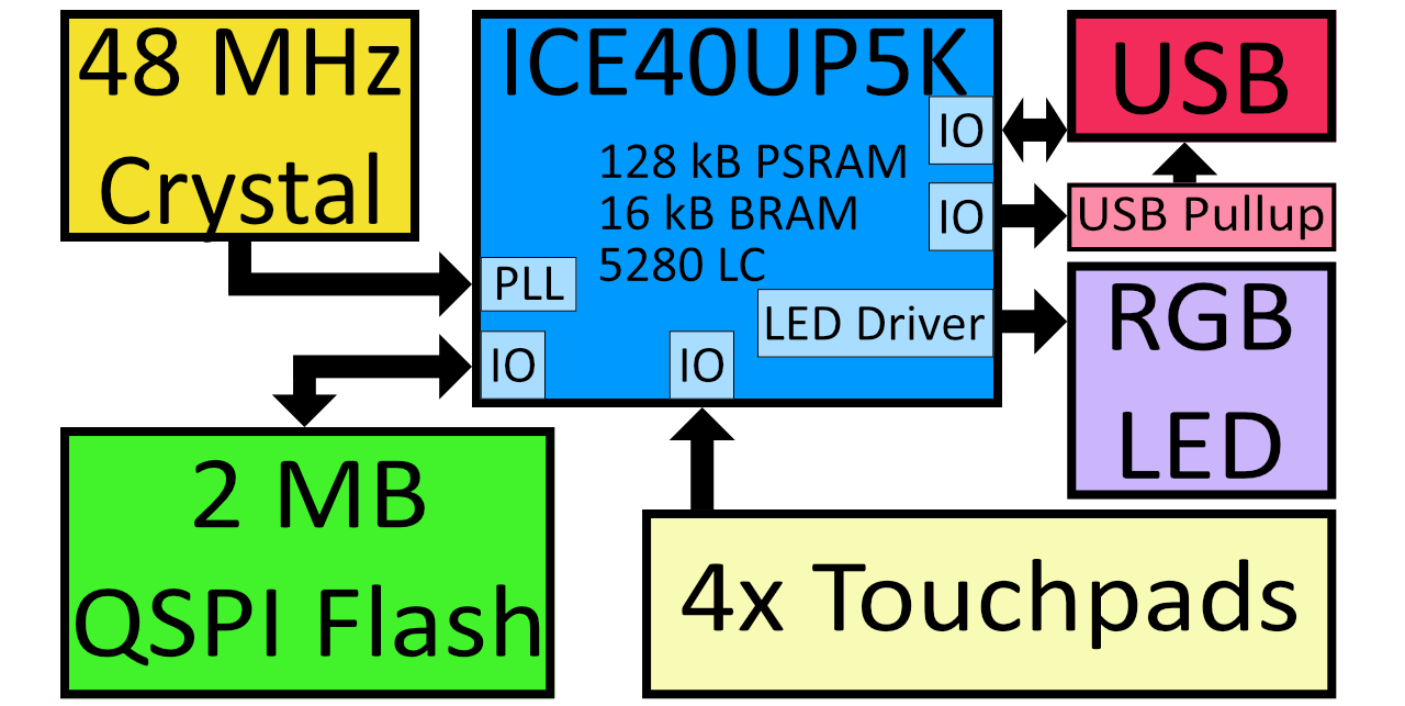
Fomu is an ICE40UP5K that fits in your USB port. It contains two megabytes of SPI flash memory, four edge buttons, and a three-color LED. Unlike most other ICE40 projects, Fomu implements its USB in a softcore. That means that the bitstream that runs on the FPGA must also provide the ability to communicate over USB. This uses up a lot of storage on this small FPGA, but it also enables us to have such a tiny form factor, and lets us do some really cool things with it.
The ICE40UP5K at the heart of Fomu really controls everything, and this workshop is all about trying to unlock the power of this chip.
There is a default bootloader that runs when you plug in Fomu. It is called foboot, and it presents itself as a DFU (Device Firmware Update) image. Future versions of Fomu will include a bootloader that shows up as an external drive, however for now we're still using DFU.
Verify the drivers were installed. Plug in your Fomu now and see if you can see it using dfu-util -l:
$ dfu-util -l
dfu-util 0.8
Copyright 2005-2009 Weston Schmidt, Harald Welte and OpenMoko Inc.
Copyright 2010-2014 Tormod Volden and Stefan Schmidt
This program is Free Software and has ABSOLUTELY NO WARRANTY
Please report bugs to [email protected]

Found DFU: [1209:5bf0] ver=0101, devnum=21, cfg=1, intf=0, alt=0, name="Fomu Hacker running DFU Bootloader v1.8.8", serial="UNKNOWN"
$
If you get the above message, it means your computer has successfully detected Fomu!
If you get a permission denied or Cannot open DFU device 1209:5bf0 error then see the next two sections. You may see additional lines in the output, depending on your harware configuration. For example, some Thinkpad laptops might give you an additional message such as Cannot open DFU device 0a5c:21f3. These messages can safely be ignored -- the only device we're interested in is 1209:5bf0.
If you're running a version of Windows earlier than Windows 10, you may need to install additional drivers.
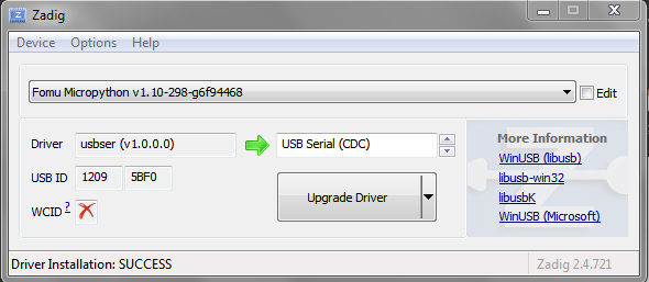
Download Zadig. Open Zadig. Under Options, select "List All Devices". In the dropdown, select your Fomu and in the field right of the green arrow choose the WinUSB driver and hit Upgrade Driver.
In Linux, try running sudo dfu-util -l, and if you get an error message, you should add a udev rule as to give your user permission to the usb device.
sudo groupadd plugdev
sudo usermod -a -G plugdev $USER
You will need to log out and log in again in order to be a member of the plugdev group.
You can check with id $USER if your user really is in the plugdev group.
Create a file named /etc/udev/rules.d/99-fomu.rules and add the
following:
SUBSYSTEM=="usb", ATTRS{idVendor}=="1209", ATTRS{idProduct}=="5bf0", MODE="0664", GROUP="plugdev"
You can reload the udev-rules using the following:
sudo udevadm control --reload-rules
sudo udevadm trigger
To load a binary image onto Fomu, we use the -D option:
$ dfu-util -D file.dfu
Copyright 2005-2009 Weston Schmidt, Harald Welte and OpenMoko Inc.
Copyright 2010-2014 Tormod Volden and Stefan Schmidt
This program is Free Software and has ABSOLUTELY NO WARRANTY
Please report bugs to [email protected]

Match vendor ID from file: 1209
Match product ID from file: 5bf0
Opening DFU capable USB device...
ID 1209:5bf0
Run-time device DFU version 0101
Claiming USB DFU Interface...
Setting Alternate Setting #0 ...
Determining device status: state = dfuIDLE, status = 0
dfuIDLE, continuing
DFU mode device DFU version 0101
Device returned transfer size 1024
Copying data from PC to DFU device
Download        [=========================] 100%       132908 bytes
Download done.
After the image is loaded, Fomu will start the new image. You can load RISC-V code or an ICE40 bitstream.
To restart Fomu, unplug it and plug it back in. This will start the bootloader. To run the program on Fomu without needing to load it again, use the -e option:
$ dfu-util -e
Copyright 2005-2009 Weston Schmidt, Harald Welte and OpenMoko Inc.
Copyright 2010-2014 Tormod Volden and Stefan Schmidt
This program is Free Software and has ABSOLUTELY NO WARRANTY
Please report bugs to [email protected]

Opening DFU capable USB device...
ID 1209:5bf0
Run-time device DFU version 0101
Claiming USB DFU Interface...
Setting Alternate Setting #0 ...
Determining device status: state = dfuIDLE, status = 0
dfuIDLE, continuing
DFU mode device DFU version 0101
Device returned transfer size 1024
$You can load MicroPython, a small Python implementation, onto Fomu as an ordinary RISC-V binary. A precompiled binary is located in the root of the Fomu workshop files. Use dfu-util to load it:
$ dfu-util -D micropython-fomu.dfu
Copyright 2005-2009 Weston Schmidt, Harald Welte and OpenMoko Inc.
Copyright 2010-2014 Tormod Volden and Stefan Schmidt
This program is Free Software and has ABSOLUTELY NO WARRANTY
Please report bugs to [email protected]

Opening DFU capable USB device...
ID 1209:5bf0
Run-time device DFU version 0101
Claiming USB DFU Interface...
Setting Alternate Setting #0 ...
Determining device status: state = dfuIDLE, status = 0
dfuIDLE, continuing
DFU mode device DFU version 0101
Device returned transfer size 1024
$
If you're on a macOS machine, use the following command to connect to the device:
$ screen /dev/cu.usb*If you're on Linux, it will be called ttyACM?:
$ screen /dev/ttyACM*If you're running a version of Windows earlier than Windows 10, you will need to install a driver for the serial port. Open Zadag again and select Fomu from the dropdown list. Install the driver for USB Serial (CDC). You can then use a program such as Tera Term: In Teraterm hit New Connection and select the Serial Port Radio Button. If it is greyed out you might have to change your USB Port driver for the Fomu. See Working with Fomu, above.
PS> ttermpro.exeYou should be greeted with a MicroPython banner and REPL:
MicroPython v1.10-299-g8603316 on 2019-08-19; fomu with vexriscv
>>>
This is a fully-functioning MicroPython shell. Try running some simple commands such as print() and hex(9876+1234).
Fomu's MicroPython binary contains a few extended Python modules that you can use to interact with some of the hardware. For example, the RGB LED has some predefined modes you can access. These are all located under the fomu module.
Import the fomu module and access the rgb block to change the mode to the predefined error mode:
>>> import fomu
>>> rgb = fomu.rgb()
>>> rgb.mode("error")
>>>
We can also look at some information from the SPI flash, such as the SPI ID. This ID varies between Fomu models, so it can be a good indication of what kind of Fomu your code is running on:
>>> spi = fomu.spi()
>>> hex(spi.id())
'0xc2152815'
>>>If we look at the generated Fomu header files, we can see many, many memory-mapped registers. For example, the major, minor, and revision numbers all have registers:
#define CSR_VERSION_MAJOR_ADDR 0xe0007000
#define CSR_VERSION_MINOR_ADDR 0xe0007004
#define CSR_VERSION_REVISION_ADDR 0xe0007008
#define CSR_VERSION_MODEL_ADDR 0xe0007028
These are special areas of memory that don't really exist. Instead, they correspond to hardware. We can read these values using the machine class. Read out the major, minor, and revision codes from your Fomu. They may be different from what you see here:
>>> import machine
>>> machine.mem32[0xe0007000]
1
>>> machine.mem32[0xe0007004]
8
>>> machine.mem32[0xe0007008]
7
>>>
The CSR_VERSION_MODEL_ADDR contains a single character that indicates what version of the hardware you have. We can convert this to a character and print it out.
If you have a production board you will get P as shown below;
>>> chr(machine.mem32[0xe0007028])
'P'
>>>
If you have a hacker board you will get H as shown below;
>>> chr(machine.mem32[0xe0007028])
'H'
>>>The blinking LED is actually a hardware block from Lattice. It has control registers, and we can modify these registers by writing to memory in Fomu. Some of these registers control things such as the timing of the fade in and fade out pulses, and some control the level of each of the three colors.
There is a wrapper in Fomu's MicroPython that simplifies the process of writing to these registers. The first argument is the register number, and the second argument is the value to write.
For the LEDDPWR registers, the second argument determines the brightness, value ranges from 0 to 255.
Try changing the color of the three LEDs:
>>> ADDR_RED_LED_PULSE_WIDTH   = 0b0001 # LEDDPWRR
>>> ADDR_GREEN_LED_PULSE_WIDTH = 0b0010 # LEDDPWRG
>>> ADDR_BLUE_LED_PULSE_WIDTH  = 0b0011 # LEDDPWRB
>>> rgb.write_raw(ADDR_RED_LED_PULSE_WIDTH, 255)  # Red LED fully on
>>> rgb.write_raw(ADDR_GREEN_LED_PULSE_WIDTH, 14) # Green LED mostly off
>>> rgb.write_raw(ADDR_BLUE_LED_PULSE_WIDTH, 1)   # Blue LED off
>>>
The color should change immediately. More information on these registers can be found in the ICE40 LED Driver Usage Guide.
The MicroPython interface is simply a RISC-V program. It interacts with the RISC-V softcore inside Fomu by reading and writing memory directly.
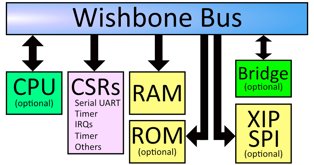
The CPU in Fomu is built on LiteX, which places every device on a Wishbone bus. This is a 32-bit internal bus that maps peripherals into memory.
If you look at the diagram above, you can see that everything in the system is on the Wishbone bus. The CPU is a bus master, and can initiate reads and writes. The system's RAM is on the wishbone bus, and is currently located at address 0x10000000. The boot ROM is also on the bus, and is located at 0x00000000. There is also SPI flash which is memory-mapped, so when you load your program onto the SPI flash it shows up on the Wishbone bus at offset 0x20040000.
The Configuration and Status Registers (CSRs) all show up at offset 0xe0000000. These are the registers we were accessing from Python. Just like before, these special memory addresses correspond to control values.
You'll notice a "Bridge" in the diagram above. This is an optional feature that we ship by default on Fomu. It bridges the Wishbone bus to another device. In our case, it makes Wishbone available over USB.
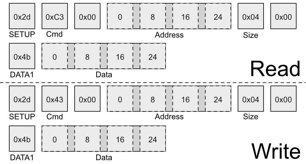
The above image shows the structure of a special USB packet we can generate to access the Wishbone bus from a host PC. It lets us do two things: Read a 32-bit value from Wishbone, or write a 32-bit value to Wishbone. These two primitives give us complete control over Fomu.
Recall these definitions from earlier:
#define CSR_VERSION_MAJOR_ADDR 0xe0007000
#define CSR_VERSION_MINOR_ADDR 0xe0007004
#define CSR_VERSION_REVISION_ADDR 0xe0007008
#define CSR_VERSION_MODEL_ADDR 0xe0007028
We can use the wishbone-tool program to read these values directly out of Fomu:
$ wishbone-tool 0xe0007000
Value at e0007000: 00000001
$ wishbone-tool 0xe0007004
Value at e0007004: 00000008
$ wishbone-tool 0xe0007008
Value at e0007008: 00000007
$
The three values correspond to the version number of the board at time of writing: v1.8.7.
We can also read and write directly to memory. Recall that memory is mapped to address 0x10000000. Let's write a test value there and try to read it back.
$ wishbone-tool 0x10000000
Value at 10000000: 00000005
$ wishbone-tool 0x10000000 0x12345678
$ wishbone-tool 0x10000000
Value at 10000000: 0x12345678
We can see that the value got stored in memory, just like we thought it would. The bridge is working, and we have access to Fomu over USB.
Recall the LED block from Python. We used rgb.write_raw() to write values to the LED block. Because of how the LED block is implemented, we need to actually make two writes to the Wishbone bus in order to write one value to the LED block. The first write sets the address, and the second write sends the actual data.
The registers for the LED block are defined as:
#define CSR_RGB_DAT_ADDR 0xe0006800
#define CSR_RGB_ADDR_ADDR 0xe0006804
Let's change the red color to the maximum value. To do that, we'll write a 1 to the address register, and 0xff to the data register:
$ wishbone-tool 0xe0006804 1
$ wishbone-tool 0xe0006800 0xff
We can see that the LED immediately changed its behavior. Try playing around with various values to see what combinations you can come up with!
You can reset Fomu by writing a special value to the CSR_REBOOT_CTRL register at 0xe0006000L. All writes to this register must start with 0xac, to ensure random values aren't written. We can reboot Fomu by simply writing this value:
$ wishbone-tool 0xe0006000 0xac
INFO [wishbone_tool::usb_bridge] opened USB device device 007 on bus 001
INFO [wishbone_tool::usb_bridge] waiting for target device
ERROR [wishbone_tool] server error: BridgeError(USBError(Pipe))
$
We can see that wishbone-tool has crashed with an error of USBError(Pipe), because the USB device went away as we were talking to it. This is expected behavior. Fomu should be back to its normal color and blink rate now.
Of course, Fomu's softcore is a full CPU, so we can write C code for it. Go to the riscv-blink/ directory and run make. This will generate riscv-blink.dfu, which we can load onto Fomu.
$ make
  CC       ./src/main.c        main.o
  CC       ./src/rgb.c rgb.o
  CC       ./src/time.c        time.o
  AS       ./src/crt0-vexriscv.S       crt0-vexriscv.o
  LD       riscv-blink.elf
  OBJCOPY  riscv-blink.bin
  IHEX     riscv-blink.ihex
  DFU      riscv-blink.dfu
$ dfu-util -D riscv-blink.dfu
Copyright 2005-2009 Weston Schmidt, Harald Welte and OpenMoko Inc.
Copyright 2010-2014 Tormod Volden and Stefan Schmidt
This program is Free Software and has ABSOLUTELY NO WARRANTY
Please report bugs to [email protected]

Match vendor ID from file: 1209
Match product ID from file: 5bf0
Opening DFU capable USB device...
ID 1209:5bf0
Run-time device DFU version 0101
Claiming USB DFU Interface...
Setting Alternate Setting #0 ...
Determining device status: state = dfuIDLE, status = 0
dfuIDLE, continuing
DFU mode device DFU version 0101
Device returned transfer size 1024
Copying data from PC to DFU device
Download        [======                   ]  24%        804 bytes
$
This will load the binary onto Fomu and start it immediately. The LED should be blinking quickly in a rainbow pattern. Congratulations! You've compiled and loaded a RISC-V program onto a softcore.
Let's modify the program by increasing the fade rate so much that it appears solid. First, reboot Fomu by running wishbone-tool 0xe0006000 0xac. Next, apply the following patch to src/main.c:
--- a/riscv-blink/src/main.c
+++ b/riscv-blink/src/main.c
@@ -46,6 +46,7 @@ int main(void) {
     usb_init();
     rgb_init();
     usb_connect();
+    rgb_write((100000/64000)-1, LEDDBR);
     int i = 0;
     while (1) {
         color_wheel(i++);
What this does is increase the LED blink rate from 250 Hz to a much higher value. Compile this and load it again with dfu-util -D riscv-blink.bin. The blink rate should appear solid, because it's blinking too quickly to see.
Because we have peek and poke, and because the USB bridge is a bus master, we can actually halt (and reset!) the CPU over the USB bridge. We can go even further and attach a full debugger to it!
To start with, run wishbone-tool -s gdb:
$ wishbone-tool -s gdb
INFO [wishbone_tool::usb_bridge] opened USB device device 008 on bus 001
INFO [wishbone_tool::server] accepting connections on 0.0.0.0:1234
In a second window, run gdb on riscv-blink.elf:
$ riscv64-unknown-elf-gdb riscv-blink.elf -ex 'target remote localhost:1234'
GNU gdb (GDB) 8.2.90.20190228-git
Copyright (C) 2019 Free Software Foundation, Inc.
License GPLv3+: GNU GPL version 3 or later <http://gnu.org/licenses/gpl.html>
This is free software: you are free to change and redistribute it.
There is NO WARRANTY, to the extent permitted by law.
Type "show copying" and "show warranty" for details.
This GDB was configured as "--host=x86_64-w64-mingw32 --target=riscv64-unknown-elf".
Type "show configuration" for configuration details.
For bug reporting instructions, please see:
<http://www.gnu.org/software/gdb/bugs/>.
Find the GDB manual and other documentation resources online at:
    <http://www.gnu.org/software/gdb/documentation/>.

For help, type "help".
Type "apropos word" to search for commands related to "word"...
Reading symbols from .\riscv-blink.elf...
Remote debugging using localhost:1234
csr_writel (addr=3758106660, value=1) at ./include/hw/common.h:41
41              *((volatile uint32_t *)addr) = value;
(gdb)
If we run bt we can get a backtrace, and chances are that we landed in an msleep function:
(gdb) bt
#0  0x2004014c in csr_readl (addr=3758106664) at ./include/hw/common.h:46
#1  timer0_value_read () at ./include/generated/csr.h:242
#2  0x200401dc in msleep (ms=ms@entry=80) at ./include/hw/common.h:41
#3  0x20040074 in main () at ./src/main.c:45
(gdb)
We can insert breakpoints, step, continue execution, and generally debug the entire system. We can even reset the program by running mon reset.
There is an additional RISC-V demo in the workshop. The riscv-usb-cdcacm directory contains a simple USB serial device that simply echoes back any characters that you type, incremented by 1. This is a good way to get started with an interactive terminal program, or logging data via USB serial.
The two most common Hardware Description Languages are Verilog and VHDL (the toolchain we are using only supports Verilog).
The canonical "Hello, world!" of hardware is to blink an LED. The directory verilog-blink contains a Verilog example of a blink project. This takes the 48 MHz clock and divides it down by a large number so you get an on/off pattern. It also exposes some of the signals on the touchpads, making it possible to probe them with an oscilloscope.
Enter the verilog-blink directory and build the verilog-blink demo by using make:
Make sure you set the FOMU_REV value to match your hardware! See the Required Hardware section.
$ make FOMU_REV=$FOMU_REV
...
Info: Max frequency for clock 'clk': 79.76 MHz (PASS at 12.00 MHz)

Info: Max delay <async>     -> <async>: 13.29 ns
Info: Max delay posedge clk -> <async>: 6.46 ns

Info: Slack histogram:
Info:  legend: * represents 1 endpoint(s)
Info:          + represents [1,1) endpoint(s)
Info: [ 70046,  70496) |*
Info: [ 70496,  70946) |*
Info: [ 70946,  71396) |**
Info: [ 71396,  71846) |**
Info: [ 71846,  72296) |**
Info: [ 72296,  72746) |**
Info: [ 72746,  73196) |
Info: [ 73196,  73646) |*
Info: [ 73646,  74096) |*
Info: [ 74096,  74546) |**
Info: [ 74546,  74996) |**
Info: [ 74996,  75446) |*
Info: [ 75446,  75896) |*
Info: [ 75896,  76346) |
Info: [ 76346,  76796) |**
Info: [ 76796,  77246) |***
Info: [ 77246,  77696) |*
Info: [ 77696,  78146) |*
Info: [ 78146,  78596) |
Info: [ 78596,  79046) |*************************
4 warnings, 0 errors
 PACK     blink.bin
Built 'blink' for Fomu XXXXX
$
You can load blink.bin onto Fomu by using the same dfu-util -D command we've been using. The LED should begin blinking on and off regularly, indicating your bitstream was successfully loaded.
When writing HDL, a tool called
yosysis used to convert the human readable verilog into a netlist representation, this is called synthesis. Once we have the netlist representation a tool callednextpnrperforms an operation called "place and route" which makes it something that will actually run on the FPGA. This is all done for you using theMakefilein theverilog-blinkdirectory.A big feature of
nextpnrover its predecessor, is the fact that it is timing-driven. This means that a design will be generated with a given clock domain guaranteed to perform fast enough.When the
makecommand runsnextpnr-ice40you will see the following included in the output;Max frequency for clock 'clk12': 24.63 MHz (PASS at 12.00 MHz) Max frequency for clock 'clk48_1': 60.66 MHz (PASS at 48.00 MHz) Max frequency for clock 'clkraw': 228.05 MHz (PASS at 48.00 MHz)This output example above shows we could run
clk12at up to 24.63 MHz and it would still be stable, even though we only requested 12.00 MHz. Note that there is some variation between designs depending on how the placer and router decided to lay things out, so your exact frequency numbers might be different.
FIXME: Add the Migen and LiteX equivalent for the Verilog above.
Migen is an HDL embedded in Python, and LiteX provides us with a Wishbone abstraction layer. There really is no reason we need to include a CPU with our design, but we can still reuse the USB Wishbone bridge in order to write HDL code.
We can use DummyUsb to respond to USB requests and bridge USB to Wishbone, and rely on LiteX to generate registers and wire them to hardware signals. We can still use wishbone-tool to read and write memory, and with a wishbone bridge we can actually have code running on our local system that can read and write memory on Fomu.
Go to the litex directory and build the design;
$ python3 workshop.py --board $FOMU_REV
lxbuildenv: v2019.8.19.1 (run .\workshop.py --lx-help for help)
lxbuildenv: Skipping git configuration because "skip-git" was found in LX_CONFIGURATION
lxbuildenv: To fetch from git, run .\workshop.py --placer heap --lx-check-git
Warning: Wire top.basesoc_adr has an unprocessed 'init' attribute.
Warning: Wire top.basesoc_bus_wishbone_ack has an unprocessed 'init' attribute.
Warning: Wire top.basesoc_bus_wishbone_dat_r has an unprocessed 'init' attribute.
...
Info: Device utilisation:
Info:            ICESTORM_LC:  1483/ 5280    28%
Info:           ICESTORM_RAM:     1/   30     3%
Info:                  SB_IO:     4/   96     4%
Info:                  SB_GB:     8/    8   100%
Info:           ICESTORM_PLL:     1/    1   100%
Info:            SB_WARMBOOT:     0/    1     0%
Info:           ICESTORM_DSP:     0/    8     0%
Info:         ICESTORM_HFOSC:     0/    1     0%
Info:         ICESTORM_LFOSC:     0/    1     0%
Info:                 SB_I2C:     0/    2     0%
Info:                 SB_SPI:     0/    2     0%
Info:                 IO_I3C:     0/    2     0%
Info:            SB_LEDDA_IP:     0/    1     0%
Info:            SB_RGBA_DRV:     0/    1     0%
Info:         ICESTORM_SPRAM:     4/    4   100%
...
Info: [ 55530,  59533) |********+
Info: [ 59533,  63536) |************************************************+
Info: [ 63536,  67539) |******************************+
Info: [ 67539,  71542) |*************+
Info: [ 71542,  75545) |********************+
Info: [ 75545,  79548) |************************************************************
5 warnings, 0 errors
Load it onto Fomu:
$ dfu-util -D build/gateware/top.dfu
dfu-util 0.8
Copyright 2005-2009 Weston Schmidt, Harald Welte and OpenMoko Inc.
Copyright 2010-2014 Tormod Volden and Stefan Schmidt
This program is Free Software and has ABSOLUTELY NO WARRANTY
Please report bugs to [email protected]

Opening DFU capable USB device...
ID 1209:5bf0
Run-time device DFU version 0101
Claiming USB DFU Interface...
Setting Alternate Setting #0 ...
Determining device status: state = dfuIDLE, status = 0
dfuIDLE, continuing
DFU mode device DFU version 0101
Device returned transfer size 1024
Copying data from PC to DFU device
Download        [=========================] 100%       104090 bytes
Download done.
state(7) = dfuMANIFEST, status(0) = No error condition is present
state(8) = dfuMANIFEST-WAIT-RESET, status(0) = No error condition is present
Done!
$
If you get an error message about missing modules, check you have all submodules cloned and setup with;
$ git submodule update --recursive --init
$
Take a look at build/csr.csv. This describes the various regions present in our design. You can see memory_region,sram,0x10000000,131072, which indicates the RAM is 128 kilobytes long and is located at 0x10000000, just as when we had a CPU. You can also see the timer, which is a feature that comes as part of LiteX. Let's try reading and writing RAM:
$ wishbone-tool 0x10000000
Value at 10000000: 0baf801e
$ wishbone-tool 0x10000000 0x98765432
$ wishbone-tool 0x10000000
Value at 10000000: 98765432
$
Aside from that, there's not much we can do with this design. But there's a lot of infrastructure there. So let's add something.
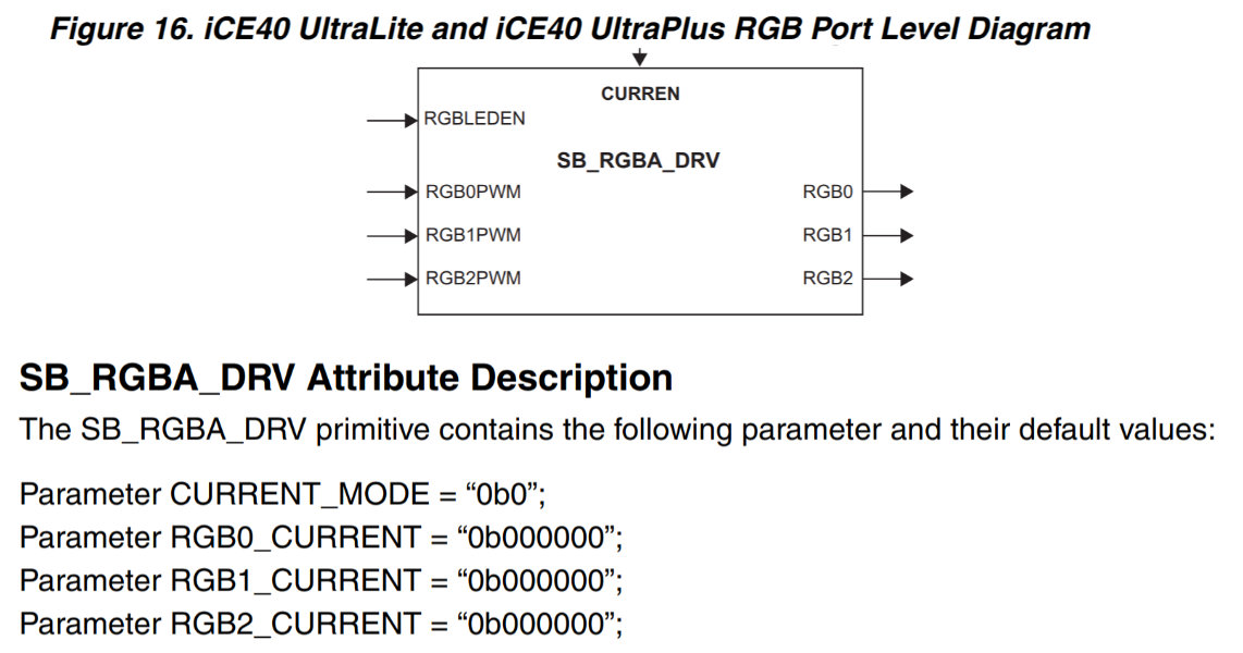
This is the RGB block from the datasheet. It has five inputs: CURREN, RGBLEDEN, RGB0PWM, RGB1PWM, and RGB2PWM. It has three outputs: RGB0, RGB1, and RGB2. It also has four parameters: CURRENT_MODE, RGB0_CURRENT, RGB1_CURRENT, and RGB2_CURRENT.
This block is defined in Verilog, but we can very easily import it as a Module into Migen:
class FomuRGB(Module, AutoCSR):
    def __init__(self, pads):
        self.output = CSRStorage(3)
        self.specials += Instance("SB_RGBA_DRV",
            i_CURREN = 0b1,
            i_RGBLEDEN = 0b1,
            i_RGB0PWM = self.output.storage[0],
            i_RGB1PWM = self.output.storage[1],
            i_RGB2PWM = self.output.storage[2],
            o_RGB0 = pads.r,
            o_RGB1 = pads.g,
            o_RGB2 = pads.b,
            p_CURRENT_MODE = "0b1",
            p_RGB0_CURRENT = "0b000011",
            p_RGB1_CURRENT = "0b000011",
            p_RGB2_CURRENT = "0b000011",
        )
This will instantiate this Verilog block and connect it up. It also creates a CSRStorage object that is three bits wide, and assigns it to output. By having this derive from AutoCSR, the CSRStorage will have CSR bus accessor methods added to it automatically. Finally, it wires the pads up to the outputs of the block.
We can instantiate this block by simply creating a new object and adding it to self.specials in our design:
...
    # Add the LED driver block
    led_pads = soc.platform.request("rgb_led")
    soc.submodules.fomu_rgb = FomuRGB(led_pads)
Finally, we need to add it to the csr_map:
...
    soc.add_csr("fomu_rgb")
Now, when we rebuild this design and check build/csr.csv we can see our new register:
csr_register,rgb_output,0xe0006800,1,rw
We can use wishbone-tool to write values to 0xe0006800 and see them take effect immediately.
You can see that it takes very little code to take a Signal from HDL and expose it on the Wishbone bus.
LiteX used as the soft SoC on Fomu is a very robust and scalable soft SoC platform, capable of running both bare metal binaries, Zephyr and even Linux.
It is also supported in Renode, which is an open source simulation framework that lets you run unmodified software in a fully controlled and inspectable environment. Renode is a functional simulator, which means it aims to mimic the observable behavior of the hardware instead of trying to be cycle-accurate.
We will now see how a full-blown Zephyr RTOS can be run on LiteX in Renode, and then how this simulation can be interfaced with a Fomu for a useful HW/SW co-development workflow.
Note: Apart from RISC-V and LiteX platforms, Renode supports many other architectures and platforms, as described in the documentation, which also includes a user manual and a few tutorials. You can also take a look at a Video Tutorials section on Renode's website.
Keep in mind that all platforms and configurations in Renode used in this tutorial are contained in text/config files - you can also explore Renode's usage patterns by just inspecting those files for details.
Renode is available for Linux, macOS and Windows.
On Linux and macOS, you need to have Mono installed on your computer.
You should follow the Mono installation instructions and install the mono-complete package.
On Windows it's enough to have a fairly recent .NET Framework installed.
Then you can either install Renode from prebuilt packages, or compile it yourself.
Renode comes with several precompiled demos, which can be used to verify everything works for you before starting to compile and use your own software binaries.
There are three demo scripts available:
litex_vexriscv_micropython.resclitex_vexriscv_zephyr.resclitex_vexriscv_linux.resc
To run them, start Renode using the renode command (or ./renode if you built from sources).
You will see a terminal window pop up, which is the Renode CLI, called the Monitor.
In the Monitor type:
(monitor) start @scripts/single-node/<script_name>
(where <script_name> is one of the above).
Voila! A UART analyzer window should appear and you should see LiteX booting the respective binary.
Zephyr is a very capable RTOS governed by a Linux Foundation subproject. It is very well supported on the RISC-V architecture, as well as in LiteX.
To install all the dependencies and prepare the environment for building the Zephyr application follow the official Zephyr Getting Started Guide up to point 4.
On Linux you can follow the instructions from the point 5 on installing the Software Development Toolchain.
For other operating systems, if you followed the instructions from the Required Software section of this tutorial, you should have a toolchain in PATH.
On macOS and Windows you also need to set some additional variables.
For macOS:
export ZEPHYR_TOOLCHAIN_VARIANT=cross-compile
export CROSS_COMPILE=riscv64-unknown-elf-
For Windows:
set ZEPHYR_TOOLCHAIN_VARIANT=cross-compile
set CROSS_COMPILE=riscv64-unknown-elf-
To build the shell demo application for the LiteX/VexRiscv board run the following commands on Linux and macOS:
cd ~/zephyrproject/zephyr
source zephyr-env.sh
west build -p auto -b litex_vexriscv samples/subsys/shell/shell_module/
And on Windows:
cd %HOMEPATH%\zephyrproject\zephyr
zephyr-env.cmd
west build -p auto -b litex_vexriscv samples\subsys\shell\shell_module\
The resulting ELF file will be in build/zephyr/zephyr.elf.
To run the app you just compiled, you basically need to replace the precomipled demo binary with the one you want, by setting the zephyr variable - see below.
Just like before, start Renode using the renode command (or ./renode if you built from sources).
You will see the Monitor, where you should type:
(monitor) $zephyr=@~/zephyrproject/zephyr/build/zephyr/zephyr.elf
(monitor) start @scripts/single-node/litex_vexriscv_zephyr.resc
You should see a new window pop up for the serial port. In it, you should see the Zephyr interactive shell.
In general, debugging in Renode is done with GDB just like with a physical board - you connect to a debug port and execute GDB commands as usual. For details, see the Renode debugging documentation.
This part of the workshop is based on a Renode, Fomu and Etherbone bridge example from the Renode documentation.
Just like we can access Fomu peripherals using wishbone-tool, we can also connect to a physical board from Renode, mapping a part of the memory space to be accessible via the Etherbone protocol.
This is a very useful capability as it enables us to potentially simulate an advanced LiteX SoC system which would not normally fit in the FPGA (or e.g. take a long time to synthesize), and interface it with the remaining part of the physical system for I/O.
Ensure your Fomu is plugged in and setup the Etherbone server.
In the workshop directory execute the following commands (on Linux and macOS):
cd litex/deps/litex
git checkout master && git pull # this will fetch newer LiteX, required to handle communication properly
./litex_setup.py init  # this will clone dependencies
export PYTHONPATH=`pwd`:`pwd`/litex:`pwd`/migen
When on Windows, run:
cd litex\deps\litex
git checkout master && git pull
litex_setup.py init
set PYTHONPATH=%cd%;%cd%\litex;%cd%\migen
After this preparation, we are ready to start the server:
python3 litex/tools/litex_server.py --usb --usb-vid 0x1209 --usb-pid 0x5bf0You should see the following output, confirming that the server is connected to Fomu:
LiteX remote server
[CommUSB] vid: 0x1209 / pid: 0x5bf0 / tcp port: 1234
Now you can start Renode and setup the platform.
Run renode and in the Monitor type:
(monitor) include @scripts/complex/fomu/renode_etherbone_fomu.resc
(machine-0) start
The litex_server.py should print:
Connected with 127.0.0.1:<port>
You will also see a new window with a shell application, that provides additional commands allowing you to control LEDs on Fomu.
uart:~$ led_toggle
uart:~$ led_breathe
The led_toggle command controls the LED by turning it on and off.
led_breathe makes the LED fade slowly in and out, creating a "breathe" effect.
The script you loaded configures Renode to log all communication with Fomu. After issuing some commands in Zephyr's shell you'll see:
01:00:31.8276 [DEBUG] led: [cpu: 0x40000988] WriteUInt32 to 0x8 (unknown), value 0x7.
01:00:31.8279 [DEBUG] led: [cpu: 0x40000990] WriteUInt32 to 0x4 (unknown), value 0x8.
01:00:31.8290 [DEBUG] led: [cpu: 0x40000998] WriteUInt32 to 0x0 (unknown), value 0xC8.
01:00:31.8298 [DEBUG] led: [cpu: 0x400009A0] WriteUInt32 to 0x4 (unknown), value 0x9.
01:00:31.8301 [DEBUG] led: [cpu: 0x400009A8] WriteUInt32 to 0x0 (unknown), value 0xBA.
01:00:31.8305 [DEBUG] led: [cpu: 0x400009B0] WriteUInt32 to 0x8 (unknown), value 0x6.
01:00:31.8308 [DEBUG] led: [cpu: 0x400009B4] WriteUInt32 to 0x8 (unknown), value 0x7.
01:00:31.8311 [DEBUG] led: [cpu: 0x400009BC] WriteUInt32 to 0x4 (unknown), value 0x5.
01:00:31.8314 [DEBUG] led: [cpu: 0x400009C0] WriteUInt32 to 0x0 (unknown), value 0x0.
01:00:31.8317 [DEBUG] led: [cpu: 0x400009C4] WriteUInt32 to 0x4 (unknown), value 0x6.
01:00:31.8321 [DEBUG] led: [cpu: 0x400009C8] WriteUInt32 to 0x0 (unknown), value 0x0.
01:00:31.8324 [DEBUG] led: [cpu: 0x400009D0] WriteUInt32 to 0x4 (unknown), value 0x2.
01:00:31.8327 [DEBUG] led: [cpu: 0x400009D4] WriteUInt32 to 0x0 (unknown), value 0x0.
01:00:31.8331 [DEBUG] led: [cpu: 0x400009DC] WriteUInt32 to 0x4 (unknown), value 0x3.
01:00:31.8334 [DEBUG] led: [cpu: 0x400009E0] WriteUInt32 to 0x0 (unknown), value 0x0.
01:00:31.8337 [DEBUG] led: [cpu: 0x400009E8] WriteUInt32 to 0x4 (unknown), value 0x1.
01:00:31.8341 [DEBUG] led: [cpu: 0x400009F4] WriteUInt32 to 0x0 (unknown), value 0xFF.
01:00:31.8344 [DEBUG] led: [cpu: 0x40000A08] WriteUInt32 to 0x4 (unknown), value 0xA.
01:00:31.8347 [DEBUG] led: [cpu: 0x40000A0C] WriteUInt32 to 0x0 (unknown), value 0x0.
01:00:31.8350 [DEBUG] led: [cpu: 0x40000A14] WriteUInt32 to 0x4 (unknown), value 0xB.
01:00:31.8353 [DEBUG] led: [cpu: 0x40000A18] WriteUInt32 to 0x0 (unknown), value 0xFF.
You can interact with Fomu manually, via the Monitor. To do that, you first need to find the name of the peripheral that serves the connection to Fomu.
Type in peripherals to see a list of all the elements of the emulated SoC.
Look for EtherBoneBridge entry:
(machine-0) peripherals
Available peripherals:
  sysbus (SystemBus)
  │
  ├── cpu (VexRiscv)
  │     Slot: 0
  │
  ├── ddr (MappedMemory)
  │     <0x40000000, 0x4FFFFFFF>
  │     <0xC0000000, 0xCFFFFFFF>
  │
  ├── eth (LiteX_Ethernet)
  │   │ <0x60007800, 0x600078FF>
  │   │ <0xE0007800, 0xE00078FF>
  │   │ <0x30000000, 0x30001FFF>
  │   │ <0xB0000000, 0xB0001FFF>
  │   │ <0x60007000, 0x600077FF>
  │   │ <0xE0007000, 0xE00077FF>
  │   │
  │   └── phy (EthernetPhysicalLayer)
  │         Address: 0
  │
  ├── flash_mem (MappedMemory)
  │     <0x20000000, 0x21FFFFFF>
  │     <0xA0000000, 0xA1FFFFFF>
  │
  ├── led (EtherBoneBridge)
  │     <0xE0006800, 0xE00068FF>
  │
  ├── mem (MappedMemory)
  │     <0x00000000, 0x0003FFFF>
  │     <0x80000000, 0x8003FFFF>
  │
  ├── spi (LiteX_SPI_Flash)
  │   │ <0x60005000, 0x6000500F>
  │   │ <0xE0005000, 0xE000500F>
  │   │
  │   └── flash (Micron_MT25Q)
  │
  ├── sram (MappedMemory)
  │     <0x10000000, 0x1003FFFF>
  │     <0x90000000, 0x9003FFFF>
  │
  ├── timer0 (LiteX_Timer)
  │     <0x60002800, 0x60002843>
  │     <0xE0002800, 0xE0002843>
  │
  └── uart (LiteX_UART)
        <0x60001800, 0x600018FF>
        <0xE0001800, 0xE00018FF>
The device that acts as a connector to Fomu is called led and is registered at 0xE0006800:
  ├── led (EtherBoneBridge)
  │     <0xE0006800, 0xE00068FF>
You can either use a full or relative address (via the sysbus or led objects, respectively) to communicate with the physical LED controller:
(machine-0) sysbus WriteDoubleWord 0xE0006804 0x1234 # writes 0x1234 to the given address
(machine-0) led WriteDoubleWord 0x4 0x4321 # writes 0x4321 to 0xE0006800 + 0x4
Note: the above values are just an example and won't change the LED status in any visible way. If you want to enable "breathe" effect directly from the Monitor, see the necessary sequence in the application source code.
While connecting Renode to a real FPGA gives you some interesting possibilities in testing and debugging your gateware together with your software, there is another usage scenario which is completely hardware independent - connecting functional simulation of the base system in Renode with HDL simulation of a part of the system that is under development.
To this end, Renode provides an integration layer for Verilator. A typical setup with Renode + Verilator consists of several components:
- the 'verilated' HDL code itself (e.g. a UART peripheral),
- Verilator integration library, provided as a plugin to Renode,
- shim layer in C++ connecting the above.
Currently Renode supports peripherals with the AXILite interface. Keep in mind that due to the abstract nature of bus operations in Renode, it doesn't matter what kind of bus is used on the hardware you want to simulate.
In the Renode tree you will find an example with all the elements already prepared. To run it, start Renode and type:
(monitor) include @scripts/single-node/riscv_verilated_uartlite.resc
(UARTLite) start
This script loads a RISC-V-based system with a verilated UARTLite. You can verify it by calling:
(UARTLite) sysbus WhatPeripheralIsAt 0x70000000
Antmicro.Renode.Peripherals.Verilated.VerilatedUART
To inspect the communication with the UART, run:
(UARTLite) sysbus LogPeripheralAccess uart
You will see every read and write to the peripheral displayed in the Renode log.
Please note that, despite not being a Renode-native model, the UART is also capable of displaying an analyzer window. This is because Renode adds a special support for UART-type peripherals, allowing you not only to connect bus lines, but also the TX and RX UART lines, to the Renode infrastructure.
The HDL and integration layer for this UART peripheral is available on Antmicro's GitHub.
To compile it manually, you need to have ZeroMQ (libzmq3-dev on Debian-like systems) and Verilator installed in your system.
You also need to provide a full path to the src/Plugins/VerilatorPlugin/VerilatorIntegrationLibrary directory as the INTEGRATION_DIR environment variable.
This means that you need to have a copy of Renode sources to build a verilated peripheral.
With this set up, simply run make.
Renode supports integration with Verilator via AXILite bus, but can be easily expanded to support other standards as well.
We'll briefly take a look on the integration layer implemented in sim-main.cpp.
First, the user has to decide on the bus type and peripheral type. These are provided by the integration library:
#include "src/peripherals/uart.h"
#include "src/buses/axilite.h"
A bus is a type declaring all the signals and how should they be handled on each transaction. These signals have to be connected to the signals in the HDL design:
void Init() {
    AxiLite* bus = new AxiLite();

    //=================================================
    // Init bus signals
    //=================================================
    bus->clk = &top->clk;
    bus->rst = &top->rst;
    bus->awaddr = (unsigned long *)&top->awaddr;
    bus->awvalid = &top->awvalid;
    bus->awready = &top->awready;
    bus->wdata = (unsigned long *)&top->wdata;
    bus->wstrb = &top->wstrb;
    bus->wvalid = &top->wvalid;
    bus->wready = &top->wready;
    bus->bresp = &top->bresp;
    bus->bvalid = &top->bvalid;
    bus->bready = &top->bready;
    [...]
To handle the "external" communication, the user can either use the base RenodeAgent class of one of its derivatives: for example the UART type allows you to connect RX and TX signals:
    // Init peripheral
    //=================================================
    uart = new UART(bus, &top->txd, &top->rxd, prescaler);
For more details, see the verilated uartlite repository.


