Prerequisites: PlatformIO (PIO)
- Install platformio with
pip install -U platformio(create a virtualenv if desired). Alternate install options here.
First time setup:
- Clone repository
- Pull in submodules with
git submodule initandgit submodule update. (More on working with submodules here.) - Clone the Umbelt board support package (BSP) as a sibling directory to
umbelt-sw. This is a modified version of the BSP for the Adafruit Feather Sense. - Run
pio runin theumbelt-swdirectory. This will download the Feather Sense BSP from PlatformIO's servers to PlatformIO's BSP install location, then fail to compile the Umbelt code because it's using this BSP instead of the Umbelt one. - Run
python variant_pre_build.pyto overwrite the Feather Sense BSP with the Umbelt BSP. If PIO ever reverts to the original config, which will manifest as the same compilation errors as in the previous step, just re-run this script.
Compiling, uploading to device, and monitoring serial output:
- Compile with
pio run. - Upload (and compile) with
pio run -t upload. - Monitor serial activity with
pio device monitor.
After soldering on components, it's useful to check the soldering of the motor drivers before adding the flex PCB. A test program which writes each motor output high then low repeatedly and a multimeter probing the high density connector on the board can be used to verify the soldering.
- Solder components onto the rigid PCB
- Do a basic electrical test
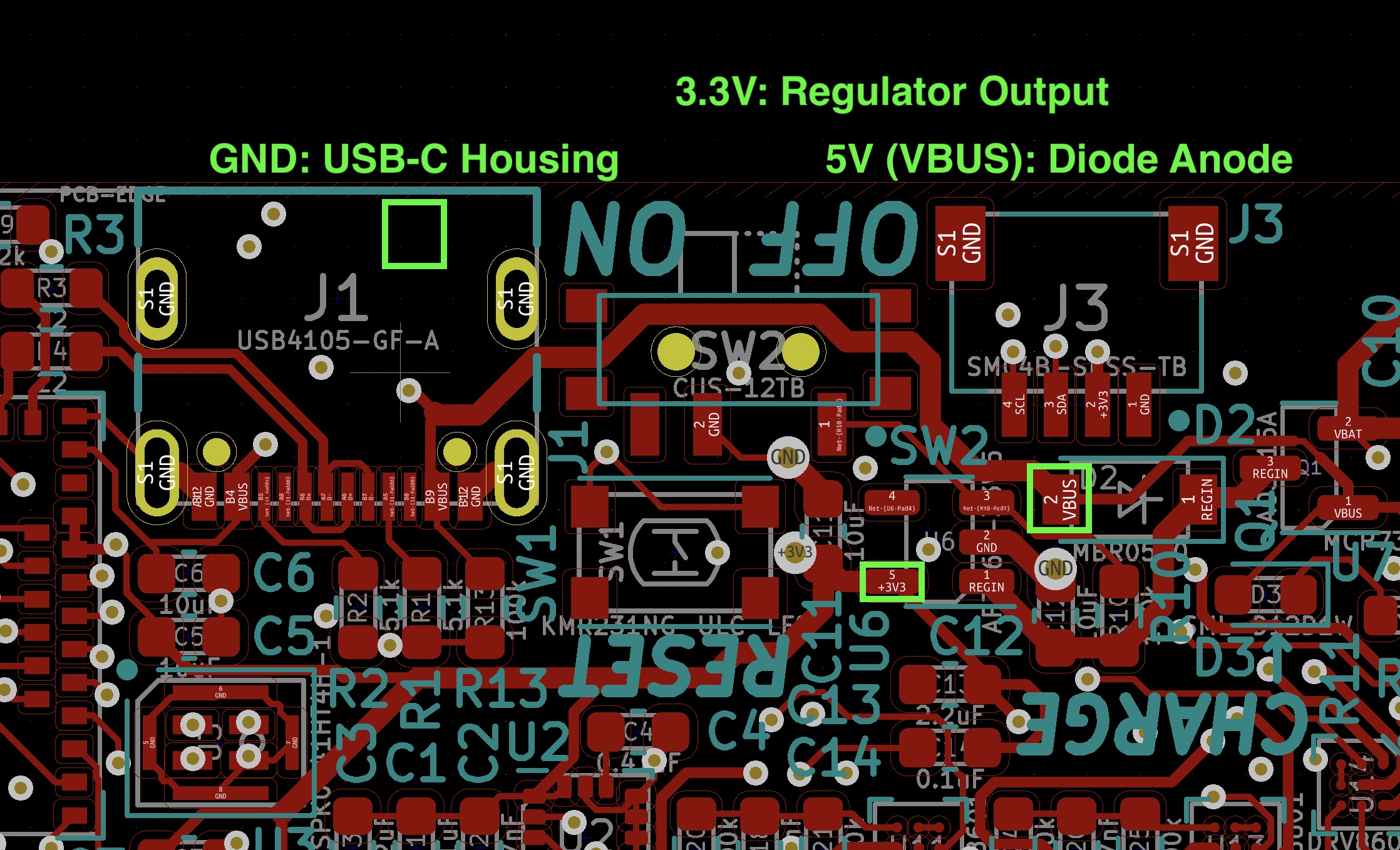
a. Check that 5V and 3V3 are not shorted to ground
- Flash the bootloader from cygann/Adafruit_nRF52_Bootloader to the umbelt.
a. Plug the board into 5V via the USB-C connector. Turn the switch to the
ONposition to enable the 3V regulator. b. Connect a J-Link to the SWD/debug port. c. Flash the bootloader withmake BOARD=feather_nrf52840_express flash. - Upload the motor testing program with
pio run -t upload -e soldertest. - Use a multimeter in DC voltage mode to probe each thin pad on the high density flex connector with the other probe on GND. Check that each motor output swings a from 0 to 3.3V. If any outputs don't do this then the soldering of the corresponding motor driver probably needs to be fixed.

For debug outputs, we strongly recommend using a jlink debug probe with RTT (Real Time Transfer) instead of Arduino's Serial library.
-
Install JLink Commander software.
-
Plug in a Segger JLink debug probe to your computer and connect the debug pins to the Umbelt board.
-
In a terminal, run
Jlinkexe -autoconnect 1 -Device NRF52840_XXAA -If SWD -Speed 400. This establishes a connection to the target chip on the Umbelt board through the Jlink debug probe. -
In another terminal window, run
JLinkRTTClientto view the debug outputs.
[TODO] On the Umblet firmware side, write to RTT with the following: