This project has as an objective the simultaneous temperature control of two fiber Bragg gratings (FBGs), which are a type of optical fiber sensor but could be easily adapted for other requirements.
We required a high-precision temperature controller. For this, a temperature controller was designed based on a Peltier, controlled with a temperature sensor as a reference and a Proportional Integrative Derivative (PID) controller that controls the power and polarity delivered through an H-Bridge.
A Peltier is a solid-state device that transfers heat from one face to the other when electrical power is applied. If the polarity is inverted, the heat transfer direction is inverted. This allows a Peltier element to be used to either cool or heat by inverting the polarity. By attaching a Peltier over a heatsink with a fan, we set one face as a reference, to be set close to ambient temperature. Then with the Peltier, we can either raise or lower the temperature of the opposite face.
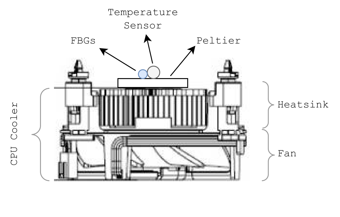
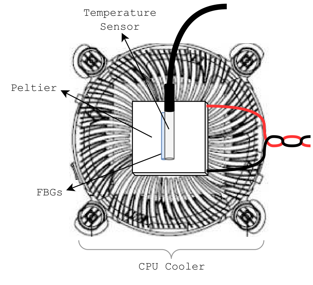
In particular, we use the cooler of a CPU, as shown in the figure below. Thermal paste is added in the interface between the heatsink and the Peltier. A temperature sensor is positioned on the top face of the Peltier with the FBGs positioned next to it. Thermal paste is added to the interface between the sensors and the Peltier, and these are fixed to the Peltier by use of insulating tape.
This Arduino code provides a flexible and configurable temperature control system using Peltier devices and PID controllers. Below are instructions on how to use and interact with the system:
-
Connect Peltier Devices: Connect the Peltier devices and the H-Bridge as explained below in section Physical layout.
-
Temperature Sensors: Connect DS18B20 temperature sensors to the OneWire bus and assign their unique addresses if necessary.
-
Buzzer: Connect a buzzer to the designated pin for audio alerts.
-
Install Required Libraries: Make sure to install the following libraries using the Arduino Library Manager:
- OneWire
- DallasTemperature
- PID_v1
-
Upload the Code: Upload the provided Arduino code to your Arduino board using the Arduino IDE or another compatible development environment.
The temperature control system can be interacted with via the Arduino's serial communication interface. Use a serial terminal (e.g., Arduino Serial Monitor) to send commands to the system. Set the baudrate to 9600.
-
Set PID Parameters (
xcommand):- Send the character
xto enter PID parameter setting mode. - Follow the on-screen prompts to adjust the PID parameters for different controllers (heaterA, coolerA, heaterB, coolerB).
- Send the character
-
Set Target Temperatures (
tcommand):- Send the character
tto set the target temperatures (setpoints) for the controllers. - Follow the on-screen prompts to enter new target temperatures for TA and TB.
- Send the character
-
Start Temperature Ramp (
scommand):- Send the character
sto start a temperature ramp. - Follow the on-screen prompts to select the ramp mode (0 OFF, 1 TA+, 2 TA-, 3 TB+, 4 TB-) and initiate the ramp.
- Send the character
-
Select Controller for Tuning (
ccommand):- Send the character
cto select a controller for tuning (heaterA, coolerA, heaterB, coolerB). - Follow the on-screen prompts to specify the controller for tuning.
- Send the character
-
The system will continuously monitor the temperature of the controlled environment and adjust the Peltier device power to maintain the desired setpoints.
-
Audio alerts will be generated by the buzzer in the event of temperature out-of-range conditions or significant temperature changes.
-
In case of out of bound temperatures or power, the system will be automatically reset.
| Temperature controller side view | Temperature controller top view |
|---|---|
 |
 |
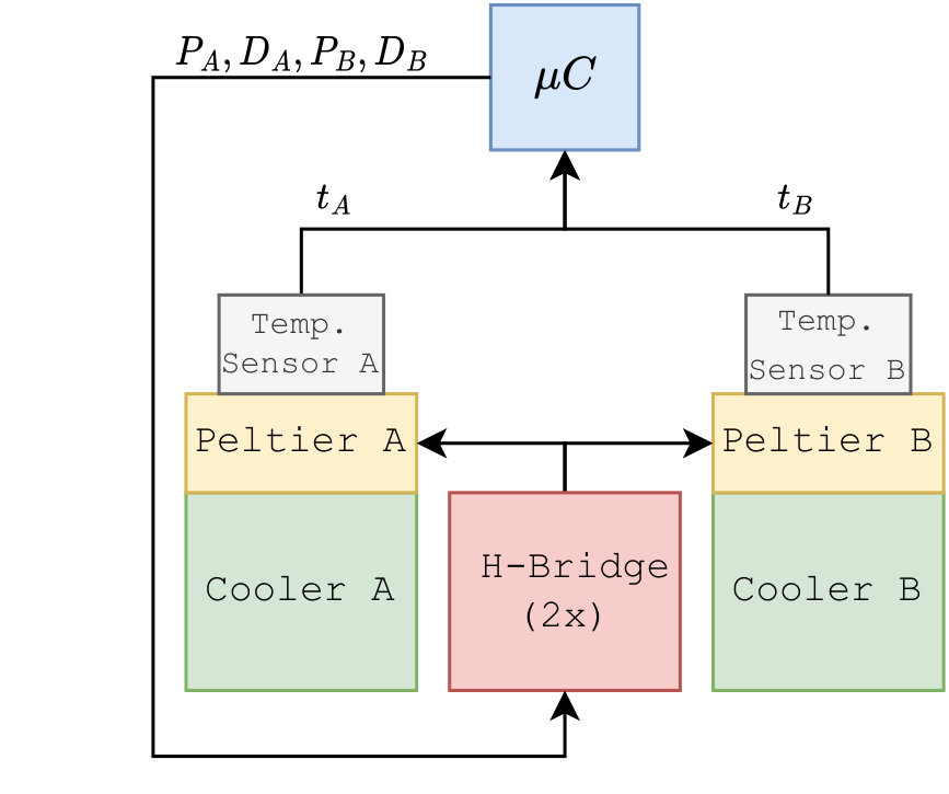
The control logic is performed by a microcontroller ($\mu$C). The information flow logic is displayed in the figure below. The polarity is set by comparing the target temperature and the ambient temperature setting the Peltier as a heater or cooler, respectively. The electrical power is controlled by a PWM signal of the microcontroller delivered to the H-Bridge. The PID updates the PWM values by looking at the difference between target temperatures and sensor temperatures. Separate PID parameters are set for cooling and heating.
| Component | Model | Characteristics |
|---|---|---|
| Temperature Sensor | DS18B20 |
|
| H-Bridge | L298N |
|
| Microcontroller | Arduino Uno R3 | |
| Peltier | TEC1-12706 |
|

