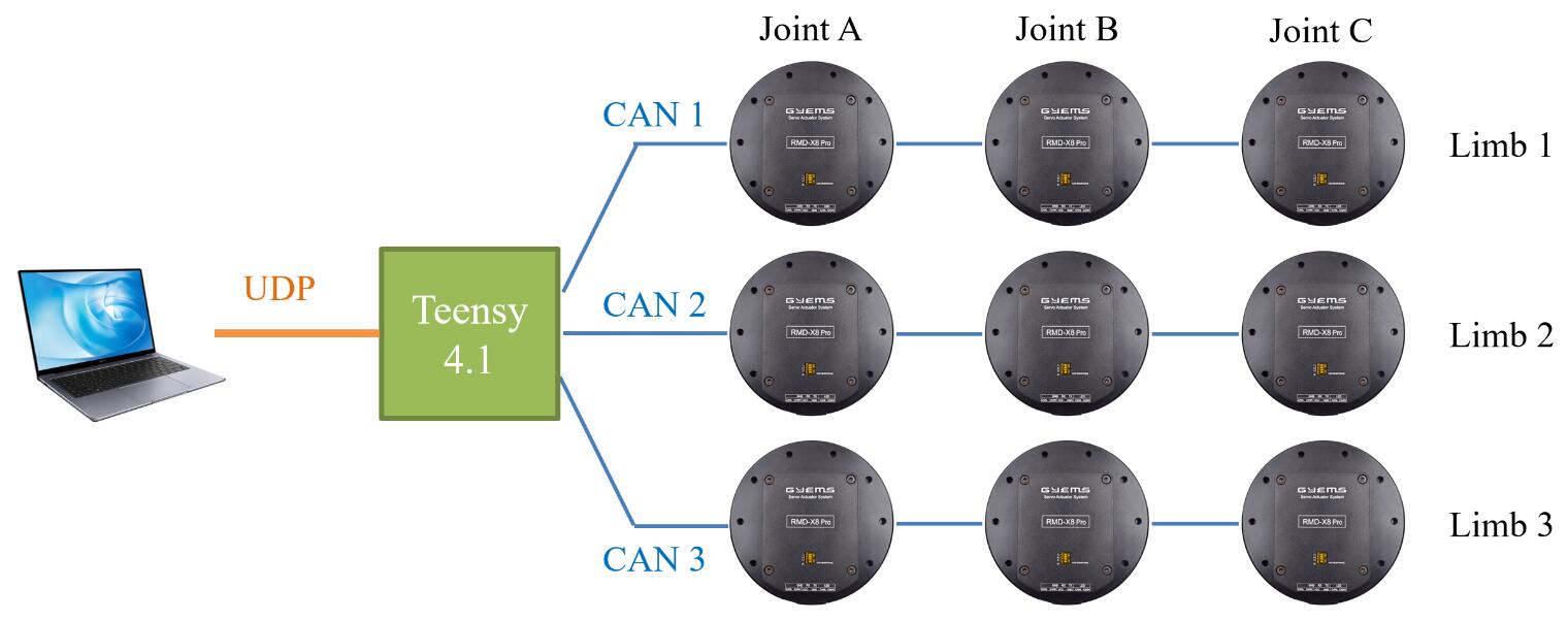
This repository functions as a hardware bridge between high-level controllers with Ethernet Ports and GYEMS-RMD motors with CAN BUS Protocol. You can directly send torque commands to up to 9 motors and receive feedback data, such as position, velocity and actual torque. In the future, other sensor data will be also intergrated here in the same way.
1_Motor_CAN: CAN BUS protocol of motors to write command and read data2_Motor_CAN_UDP: ~, UDP protocol to communicate with high-level controllers3_Motor_CAN_UDP_RTOS: ~, real-time system to schedule tasksdemo: example codes of high-level control (C/C++, MATLAB, Python)doc: figurestutorial: Arduino offical tutorials
-
Teensy 4.1 - 600MHz, 8 serial, 3 SPI, 3 I2C, 3 CAN BUS, an Ethernet 10/100 Mbit
-
Carrier Board - Official or Self-customized
-
IDE - PlatformIO
-
IDE Setup - Teensyduino
-
CAN BUS - FlexCAN_T4
-
UDP - NativeEthernet, FNET
-
RTOS - FreeRTOS-Teensy4
1) Clone this repository on your PC or controller, build the Arduino project in 3_Motor_CAN_UDP_RTOS folder and then upload to Teensy. Here we take a laptop with Ubuntu 18.04 as a high-level controller. In principle the code is independend of the environment, so both Windows and Linux should be OK (not yet been tested).
2) Connect all devices together.
3) Configure you laptop's local IP as the following recommended settings once the wired network is indetified.
IPv4 - Manual
Address: 192.168.137.178
Netmask: 255.0.0.0
4) Compile and run the high-level example in demo/udp_c folder.
sudo gcc client.c -o client -lm
./client
For the permission error, run
cd ..
sudo chmod u+x ./udp_c -R
You can also find Matlab and Python version of the high-level code which fails to run due to inconsistent bytes in UDP. Welcome to help debug :-)
1) Gravity Compensation
2) Position Control
3) Energy Shaping Control (Inverted Pendulum)
The code supports GYEMS-RMD motors with CAN ID 0x141, 0x142, 0x143 which means that you must configure the motor ID to 1, 2, 3 by GYEMS software RMD V2.0.exe before starting to control motors.
- The tx message
joint commandonly includes designed torque information which takes up 48 bytes.
float tau_a_des[3];
float tau_b_des[3];
float tau_c_des[3];

int32_t flags[3];
// int32_t checksum;
- And the rx message
joint datatakes up 108 bytes.
float q_a[3];
float q_b[3];
float q_c[3];

float qd_a[3];
float qd_b[3];
float qd_c[3];

float tau_a[3];
float tau_b[3];
float tau_c[3];

// int32_t flags[3];
// int32_t checksum;
So set the send buffer to TX_SIZE_32 (64 bytes) and the receive buffer to RX_SIZE_64 (128 bytes).
The UDP rx message includes
joint command = 48 bytes
while the UDP tx message includes
joint data = 108 bytes
force data = xx
So set the receive buffer RX_MAX_SIZE to 48 bytes while TX_MAX_SIZE is 108 bytes currently. Similarly, in high-level control code, set UDP socket buffer SO_SNDBUF = 48 bytes, SO_RCVBUF = 108 bytes.
Currently only 2 threads are scheduled.
-
UDP - priority 9; 1 kHz
-
CAN BUS - priority 8; 2 kHz
-
Calibrate torque constant (Important!!!)
-
Bit checks in UDP and CAN BUS
-
Soft stop when an accident happens
-
Intergrating other sensors - IMU, force sensor
-
Remove or uncomment all
Serial.printorSerial.printlnfunctions since they affect threads running -
Debug MATLAB and Python version of high-level examples

