Elixir/ALE provides high level abstractions for interfacing to hardware peripherals on embedded platforms. If this sounds similar to Erlang/ALE, that's because it is. This library is a Elixir-ized implementation of the library. It does differ from Erlang/ALE in that the C port side has been simplified and all Raspberry PI-specific code removed. It still runs on the Raspberry PI, but it interfaces to the hardware only through Linux interfaces.
If you're natively compiling Elixir/ALE, everything should work like any other
Elixir library. Normally, you would include elixir_ale as a dependency in your
mix.exs like this:
defp deps do
  [{:elixir_ale, "~> 0.4.1"}]
end
If you just want to try it out, you can do the following:
git clone https://github.com/fhunleth/elixir_ale.git
cd elixir_ale
mix compile
iex -S mix
If you're cross-compiling, you'll need to setup your environment so that the
right C compiler is called. See the Makefile for the variables that will need
to be overridden. At a minimum, you will need to set CROSSCOMPILE,
ERL_CFLAGS, and ERL_EI_LIBDIR.
Elixir/ALE doesn't load device drivers, so you'll need to make sure that any necessary ones for accessing I2C or SPI are loaded beforehand. On the Raspberry Pi, the Adafruit Raspberry Pi I2C instructions may be helpful.
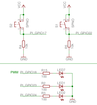
Elixir/ALE only supports simple uses of the GPIO, I2C, and SPI interfaces in Linux, but you can still do quite a bit. The following examples were tested on a Raspberry Pi that was connected to an Erlang Embedded Demo Board. There's nothing special about either the demo board or the Raspberry Pi, so these should work similarly on other embedded Linux platforms.
A GPIO is just a wire that you can use as an input or an output. It can only be one of two values, 0 or 1. A 1 corresponds to a logic high voltage like 3.3 V and a 0 corresponds to 0 V. The actual voltage depends on the hardware.
Here's an example setup:
To turn on the LED that's connected to the net labelled
PI_GPIO18, you can run the following:
iex> {:ok, pid} = Gpio.start_link(18, :output)
{:ok, #PID<0.96.0>}

iex> Gpio.write(pid, 1)
:ok
Input works similarly:
iex> {:ok, pid} = Gpio.start_link(17, :input)
{:ok, #PID<0.97.0>}

iex> Gpio.read(pid)
0

# Push the button down

iex> Gpio.read(pid)
1
If you'd like to get a message when the button is pressed or released, call the
set_int function. You can trigger on the :rising edge, :falling edge or
:both.
iex> Gpio.set_int(pid, :both)
:ok

iex> flush
{:gpio_interrupt, 17, :rising}
{:gpio_interrupt, 17, :falling}
:ok
A SPI bus is a common multi-wire bus used to connect components on a circuit
board. A clock line drives the timing of sending bits between components. Bits
on the MOSI line go from the master (usually the processor running Linux) to
the slave, and bits on the MISO line go the other direction. Bits transfer
both directions simultanteously. However, much of the time, the protocol used
across the SPI bus has a request followed by a response and in these cases, bits
going the "wrong" direction are ignored.
The following shows an example ADC that reads from either a temperature sensor on CH0 or a potentiometer on CH1.
The protocol for talking to the ADC is described in the MCP3203 Datasheet. Sending a 0x64 first reads the temperature and sending a 0x74 reads the potentiometer.
# Make sure that you've enabled or loaded the SPI driver or this will
# fail.
iex> {:ok, pid} = Spi.start_link("spidev0.0")
{:ok, #PID<0.124.0>}

# Read the potentiometer

# Use binary pattern matching to pull out the ADC counts (low 12 bits)
iex> <<_::size(4), counts::size(12)>> = Spi.transfer(pid, <<0x74, 0x00>>)
<<1, 197>>

iex> counts
453

# Convert counts to volts (1023 = 3.3 V)
iex> volts = counts / 1023 * 3.3
1.461290322580645
An I2C bus is similar to a SPI bus in function, but uses fewer wires. It supports addressing hardware components and bidirectional use of the data line.
The following shows a bus IO expander connected via I2C to the processor.
The protocol for talking to the IO expander is described in the MCP23008 Datasheet. Here's a simple example of using it.
# On the Raspberry Pi, the IO expander is connected to I2C bus 1 (i2c-1).
# Its 7-bit address is 0x20. (see datasheet)
iex> {:ok, pid} = I2c.start_link("i2c-1", 0x20)
{:ok, #PID<0.102.0>}

# By default, all 8 GPIOs are set to inputs. Set the 4 high bits to outputs
# so that we can toggle the LEDs. (Write 0x0f to register 0x00)
iex> I2c.write(pid, <<0x00, 0x0f>>
:ok

# Turn on the LED attached to bit 4 on the expander. (Write 0x10 to register
# 0x09)
iex> I2c.write(pid, <<0x09, 0x10>>)
:ok

# Read all 11 of the expander's registers to see that the bit 0 switch is
# the only one on and that the bit 4 LED is on.
iex> I2c.write(pid, <<0>>)  # Set the next register to be read to 0
:ok

iex> I2c.read(pid, 11)
<<15, 0, 0, 0, 0, 0, 0, 0, 0, 17, 16>>

# The operation of writing one or more bytes to select a register and
# then reading is very common, so a shortcut is to just run the following:
iex> I2c.write_read(pid, <<0>>, 11)
<<15, 0, 0, 0, 0, 0, 0, 0, 0, 17, 16>>

# The 17 in register 9 says that bits 0 and bit 4 are high
# We could have just read register 9.

iex> I2c.write_read(pid, <<9>>, 1)
<<17>>
This library draws much of its design and code from the Erlang/ALE project which is licensed under the Apache License, Version 2.0. As such, it is licensed similarly.


