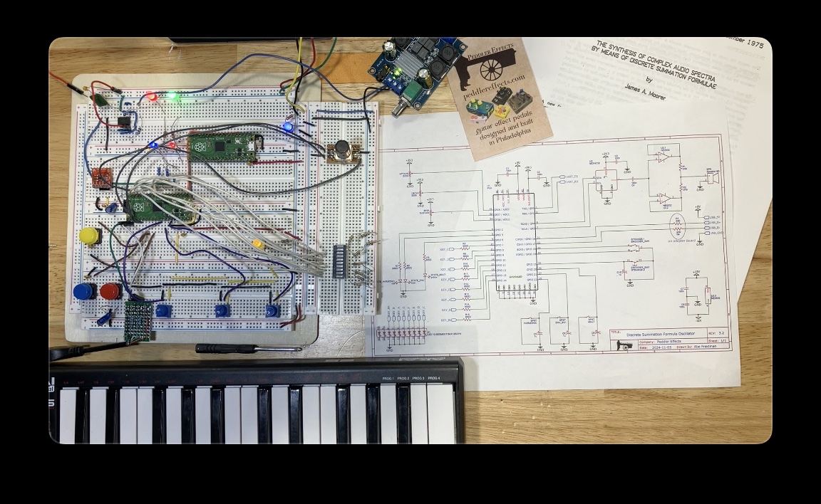
Digital audio synthesis oscillator based on James A. Moorer's 1975 paper "The Synthesis of Complex Audio Spectra by Means of Discrete Summation Formulae;" coded for Raspberry Pi Pico.
I first learned about this synthesis method from Prof. Aaron Lanterman's video where he explained the method and demonstrated some code for a software-only implementation.
/dsf-oscillator-picoLibrary source, CMakeLists.txt for example program/incHeader file definingfix15type and necessary conversion and arithmetic macros/example/lib/MCP4725_PICODAC library (see "Dependencies" below)/pico_encoderRotary encoder library (see "Dependencies" below)/usb_midi_hostUSB-MIDI host library (see "Dependencies" below)
/srcExample source code
/resourcesHardware schematic for example program, Documentation images
The DsfOsc object generates audio using Equation 4 in Moorer's paper:
 To improve speed, the math is implented using fixed-point arithmetic (see
 fix15.h and the detailed explanation in Hunter Adams' video lecture) and sine/cosine lookup tables.
A few constants can be found near the top of dsf-oscillator-pico.h:
two32: the value of 2^32, used to calculate the increment values for sine and cosineone15: fixed-point representation of 1, used to simplify fixed-point calculationstwo15: fixed-point representation of 2, used to simplify fixed-point calculations
Although Equation 4 specifies a < 1, I found that values close to the boundaries produced harsh sounds and limited my example code to 0.1 < a < 0.9 – but you could try other values by adjusting the values below:
param_a_max15: maximum value for theaterm used in the synthesis equationparam_a_min15: minimum value for theaterm used in the synthesis equationparam_a_range: difference betweenparam_a_max15andparam_a_min15, useful for calculating envelope timing. Calculated based on the max/min values.
I also have not tried negative values but the fix15 type is signed so you could see what happens.
The constructor takes care of a number of housekeeping/setup items:
- Store the sample rate and DAC bit depth for use later on
- Because the audio algorithm returns a value between
-1 < x < 1and the DAC needs a value between0 < x < ((2 ^ dac_bit_depth) -1), we calculate 1/2 of the maximum DAC value to use in scaling the output value properly. - The constuctor performs a one-time conversion of the sine and cosine lookup tables from
floattofix15.
sample_rate: The audio sample rate in Hzdac_bit_depth: The DAC bit depth
This method returns the next sample and should be called repeatedly from a timer whose period is 1,000,000 / sample_rate (i.e., the timer interval in microseconds).
param_a: Fixed-point representation of theaterm in the synthesis equation. This method checks the conditionparam_a_min15 < param_a < param_a_max15and limits out-of-bounds values to stay within the specified range.
getNextSample returns an unsigned 16-bit value within the initialized DAC range, which can be passed directly to the DAC.
This method sets the carrier and modulator frequencies. By default, it also resets the sine and cosine counters to zero; pass a false value for reset to override this behavior.
freqNote: fixed-point carrier frequency in HzfreqMod: fixed-point modulator frequency in Hzreset: iftrue, resets sine and cosine counters to zero
This overload allows you to alter the modulator frequency without changing the carrier frequency. By default, it does not reset the sine and cosine counters; pass a true value for reset to override this behavior.
freqMod: fixed-point modulator frequency in Hzreset: iftrue, resets sine and cosine counters to zero. N.B.: passing atruevalue forresetwill reset BOTH counters.
This method resets both sine and cosine counters.
The example code implements a dual-mode monophonic oscillator with a built-in ADS envelope (I'm sure I could have worked out how to get R into that envelope but I didn't feel like working so hard for it) and support for USB-MIDI controllers. I built up the example so it could function completely independently, but the controls themselves are not super intuitive. For something like a Eurorack module you could go as simple as just three CV inputs for carrier, modulator, and param_a.
As a basic demonstration of the DSF Oscillator, Standard Mode uses the MIDI input note as carrier frequency and then supplies a modulator frequency that is either double or half the carrier when isHarmonic is true; when isHarmonic is false, the modulator frequency is also multiplied by sqrt(2) to create inharmonic tones. In Standard Mode there are buttons to control the modulator's multiplier and harmony as well as the envelope direction.
The DSF Oscillator opens the door to many more possibilities. To demonstrate just one, Strange Mode uses a fixed carrier frequency and then uses the MIDI input note as modulator. To switch into Strange Mode, press the rotary encoder button. Turning the encoder will select a carrier note. The code here implements 8 carrier notes because I had 8 pins left to use as LED indicators: C through B and then Bb as the final mode because jazz (yes, it's out of note order but it also seemed confusing to have just one flat. It's open source, do what you want with it). The envelope direction button still works in Strange Mode but the harmonic and multiplier functions have no effect.
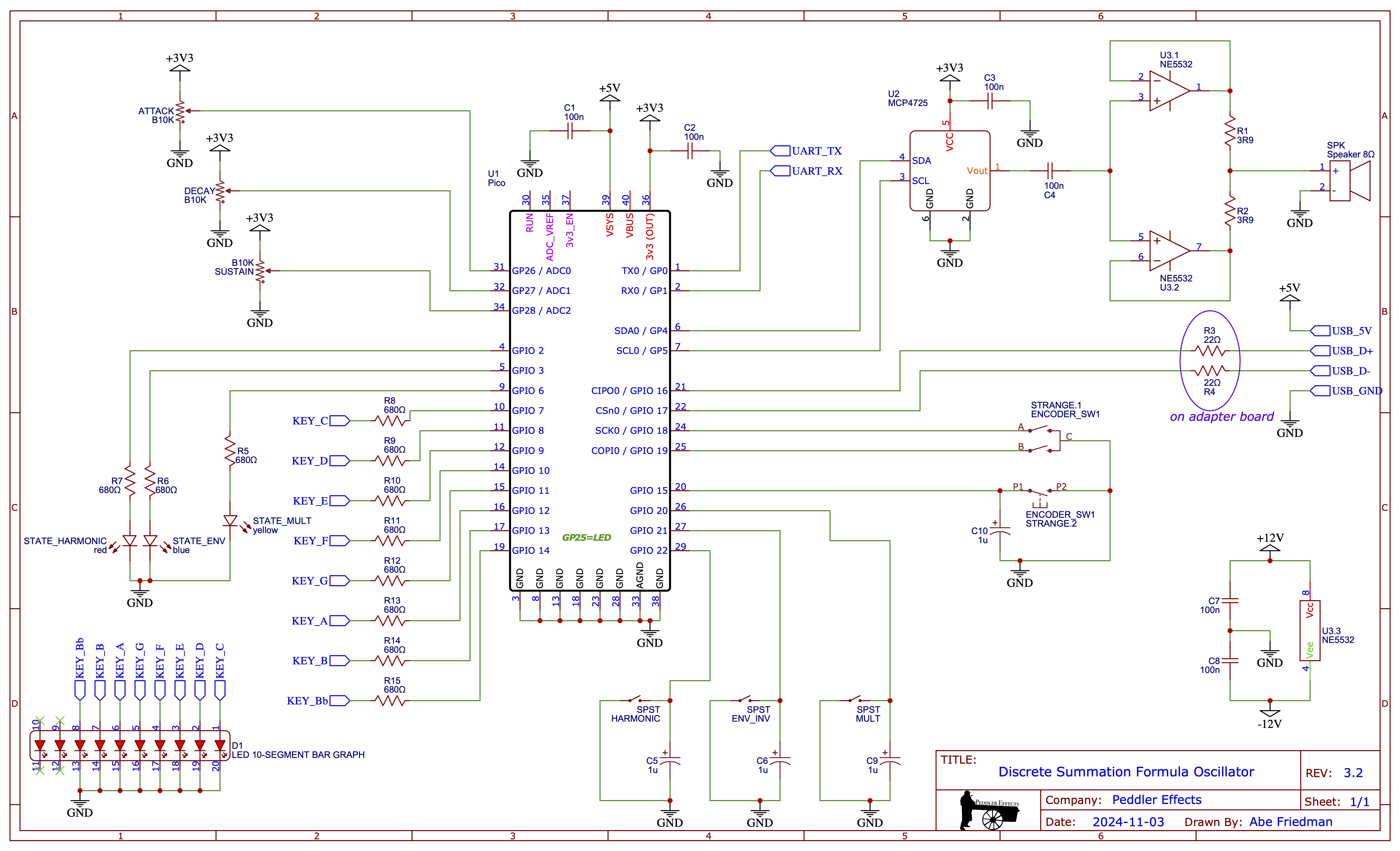
The hardware uses a rotary encoder, three push buttons, and three potentiometers for input, as well as relying on USB-MIDI for note input. Output goes through an MCP4725 12-bit i2c DAC, with two op amps in parallel driving a speaker outputting to an amplifier module (trying to drive the speaker directly from the breadboard was causing all sorts of problems). The schematic also shows hookups for indicator lights showing the state of the three bool flags controlled by the push buttons, with a key to the indicator colors shown in the demo video.
- MCP4725_PICO to control the DAC. Place in
/dsf-oscillator-pico/example/lib/MCP4725_PICO - pico_encoder for rotary encoder control over Strange Mode. Place in
/dsf-oscillator-pico/example/lib/pico_encoder - usb_midi_host for MIDI input. Place in
/dsf-oscillator-pico/example/lib/usb_midi_hostand copytusb_config.hinto/dsf-oscillator-pico/example/
VERBOSE: if true, program will output note status and debugging messages via UART serialSAMPLE_RATE: audio sample rate in HzSAMPLE_INTERVAL: timer callback interval in µs, calculated based on sample rateDAC_BIT_DEPTH: DAC bit depthI2C_SPEED: i2c bus speed in kHz, passed to MCP4725 constructor
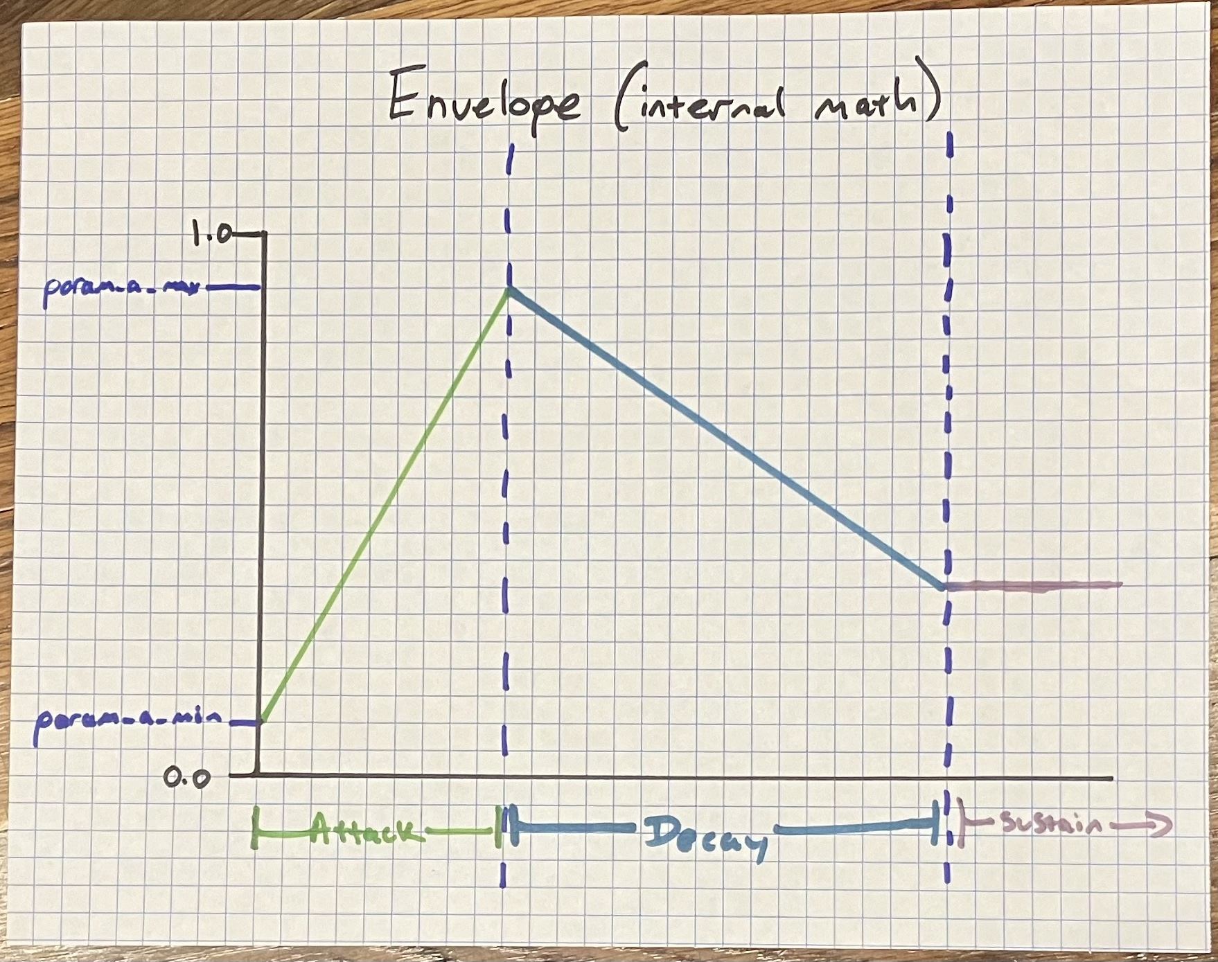
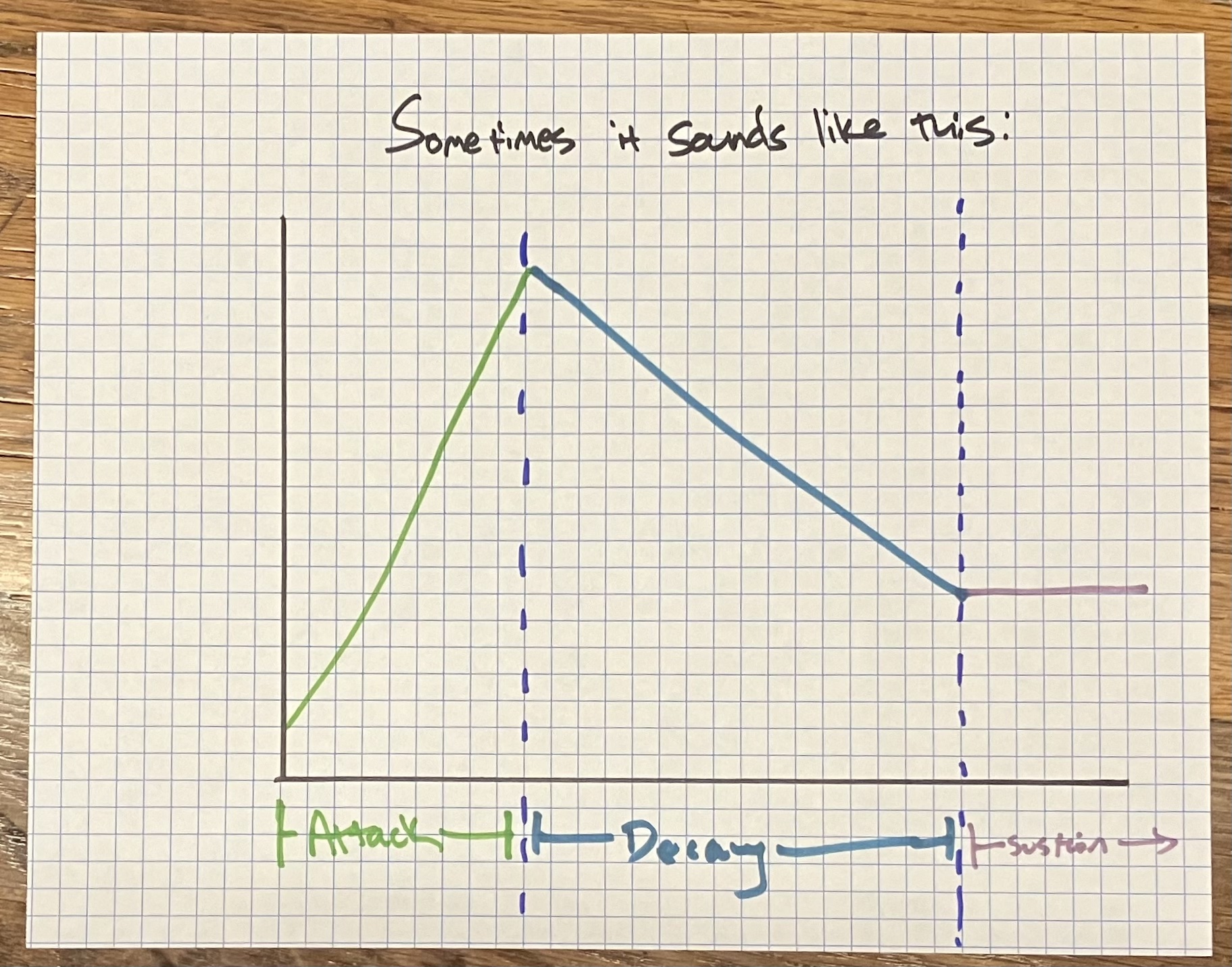
ENV_TIME_MIN: minimum Attack/Decay time in millisecondsENV_TIME_MAX: maximum Attack/Decay time in millisecondsenvelope_mode_t: enumeration of envelope modes, includesreleasein case anyone wants to implement that functionality :>envStep: constant representing the step size – could be anything, but 0.001 makes it easy to convert microsecond timekeeping into millisecond envelope durations.envRangeMin,envRangeMax: integer values setting the boundaries of how many sample timer cycles to wait before incrementing/decrementing envelope. These values are calculated by scalingENV_TIME_xbyparam_a_rangeand then dividing bySAMPLE_INTERVAL(i.e., the length between each timer call). These values are later used as the output boundaries inuscale()to calculate the actual envelope-segment timing. Using integer values here may result in envelope-length rounding errors on the order of +/-20ms. Rewriting the envelope code to usefix15instead ofuint8_twould avoid these rounding errors but I doubt I could really hear a 20ms difference so I didn't bother. Also usinguint8_tpresents a theoretical limit of 6.4s per envelope segment which seems like plenty but if you were dying for a longer envelope switching touint16_tshould get you close to a half hour per segment. You do you.envInvert: Within the envelope "Attack" indicates thatparam_ais incrementing and "Decay" indicates that it is decrementing, but the output may sound backward depending on other settings – sometimes sounding like it is "opening" during the attack phase and "closing" during the decay phase, sometimes vice versa. Behold my genius illustrations:
| what's happening internally | one way it sounds | the other way it sounds |
|---|---|---|
 |
 |
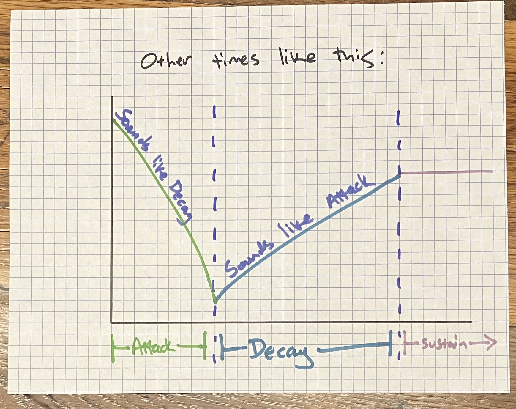 |
To me it sounds like the envelope "changes direction" depending on whether the modulator frequency is above or below the carrier frequency. It's all rock 'n' roll so whatever sounds "good" to you – I added this parameter so the user could easily invert the envelope if they want to change the envelope's apparent direction.
midi_note_t: struct holding MIDI note data and aboolflag indicating whether the note is currently activemidiFreq_Hz: array of floating-point MIDI note frequencies in HzmidiFreq15: fixed-point array that gets filled during setup with fixed-point MIDI note frequencies in HzmodFactor15: two-element array for easy access to modulator multipliers 0.5 and 2root2: fixed point representation of sqrt(2), used for inharmonic modulator frequenciesisHarmonic: state variable for whether we want harmonic or inharmonic output. When this isfalse, the modulator frequency is multiplied byroot2to get an inharmonic tone.multState: state variable that determines the relationship of carrier and modulator frequencies: half whenfalse, double whentrue. There's no real restriction on how you determine carrier vs modulator frequency (and apparently no requirement that there be any fixed relationship between the two). I picked these two values because they consistently produced musically usable tones across a wide octave range. You could substitute any other two numbers formodFactor15and get different results without changing the functional code.
strangeMode: state variable for whether we are in Strange Mode or Standard Mode.strangeModeRoots[]: eight MIDI notes to use for the carrier frequency.strangeKeyIndex: counter variable used to pick which element ofstrangeModeRoots[]to use as carrier note.
Basic setup functionality like initializing pins, filling the midiFreq15 array, etc.
Timer interrupt callback function. Does nothing unless we have an active MIDI note. When active, it follows these steps:
- Read
sustainvalue from potentiometer (will always be betweenparam_a_min15andparam_a_max15) - Determine which envelope mode we are in
- Attack:
- Read
attacktime from potentiometer - See if we've had enough cycles to increment, and if so increment the envelope
- Increment the cycle counter
- Check if we have hit or exceeded
param_a_max15. If we have, switch to Decay and reset the counter - Check if the envelope is inverted or not, and calculate the correct
param_avalue
- Read
- Decay:
- Read
decaytime from potentiometer - See if we've had enough cycles to increment, and if so increment the envelope
- Increment the cycle counter
- Check if we have hit or gone below the
sustainvalue. If we have, switch to Sustain and reset the counter - Check if the envelope is inverted or not, and calculate the correct
param_avalue
- Read
- Sustain: Check if the envelope is inverted or not, and calculate the correct
param_avalue.
- Attack:
- Pass the newly calculated
param_ato the oscillator and store the returned sample value - Send the sample value to the DAC
I added some error checking for out-of-bound DAC values but at this point I am fairly confident that the oscillator can't return an invalid value and you could probably just pass the return value from osc.getNextSample() directly to the DAC.
Button interrupt callback function.
Blinks onboard LED the number of times specified by count; if count == 0 it will blink faster and loop forever, used to signal an error in DAC initialization.
Adapted from the Arduino map() function, takes an input with a given range in_max - in_min and returns a number scaled to out_max - out_min.
Adapted from the usb_midi_host demo code. Every time a new MIDI event is received, this callback function:
- Reads MIDI data into
thisNote(n.b.: I think it will always store the first incoming event intothisNote, but I don't really have a good way to verify this hypothesis). The first (command) byte is masked so that the channel information is discarded (usb_midi_hostonly allows for one device connection so it doesn't make a difference here). - Checks the MIDI command for a "Note On" (0x9x) or "Note Off" (0x8x) message. (CC and Program Change messages are not implemented here, but it would be a simple matter to add
case 0x??:statements to theswitchblock and implement these as well). If it finds a note message: - Note On
1. Copy
thisNoteintolastNote– we will need this later on 2. SetthisNote.active = true3. Set envelope mode to Attack and reset envelope and counter to 0 4. Calculate a modulator frequency based on the MIDI note, multiplier, andisHarmonic5. Callosc.freqs()setting the carrier frequency to the MIDI note, passing the calculated modulator frequency, and setting theresetflag tofalseso we don't retrigger the sine/cosine tables when changing frequencies in case we're moving from one note directly to another. 6. Light the onboard LED to show that a note is active (this was helpful in debugging situations where there was no audio) - Note Off
1. Checks to see if
thisNote.notematcheslastNote.note– if not, we do nothing because whatever key was released is not the note currently playing. This is done so that if you hold a second note before releasing the first, releasing the first key will not interrupt the synthesis. This implementation is monophonic and will always play the most recent note. It does not "remember" earlier notes so all sound stops when you release the most recent key, even if you are still holding an earlier key. 2. If the notes match, then we mean to stop playing sothisNote.activeis set false and the onboard LED turns off.
void tuh_midi_mount_cb(uint8_t dev_addr, uint8_t in_ep, uint8_t out_ep, uint8_t num_cables_rx, uint16_t num_cables_tx)
These functions are copied without changes from the usb_midi_host demo code. See documentation there.
