See https://github.com/linorobot/linorobot2_hardware for the official readme information for the linorobot2_hardware project.
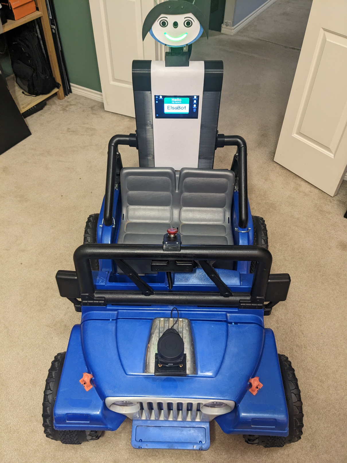
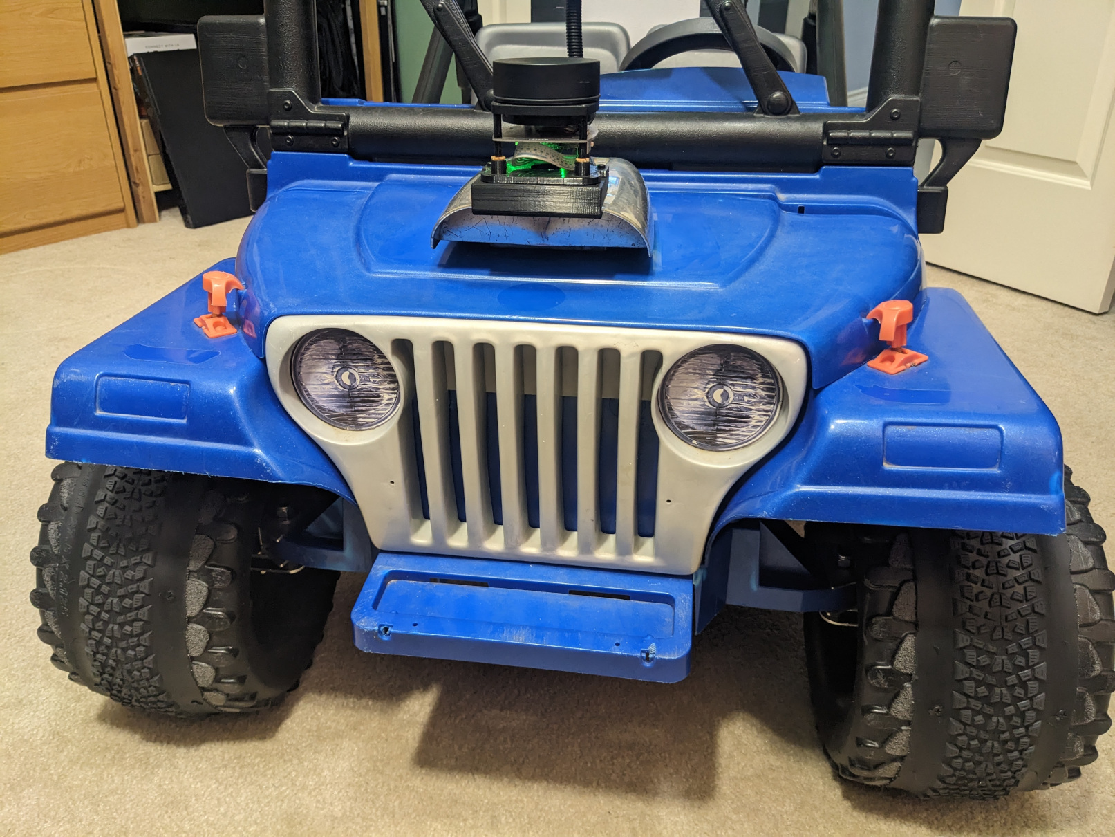
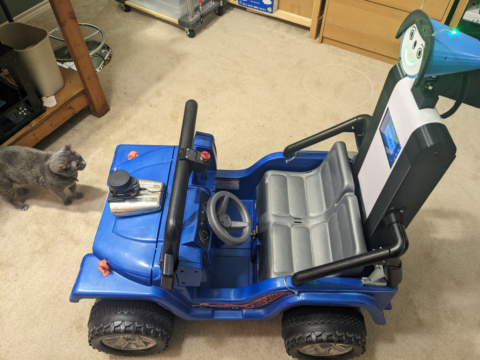
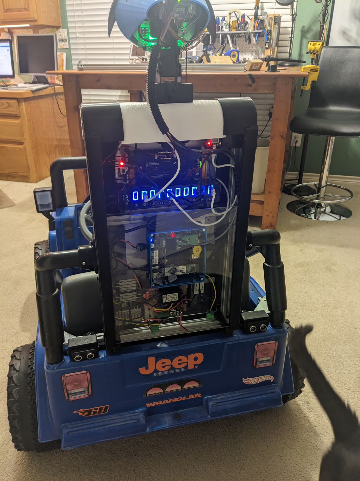
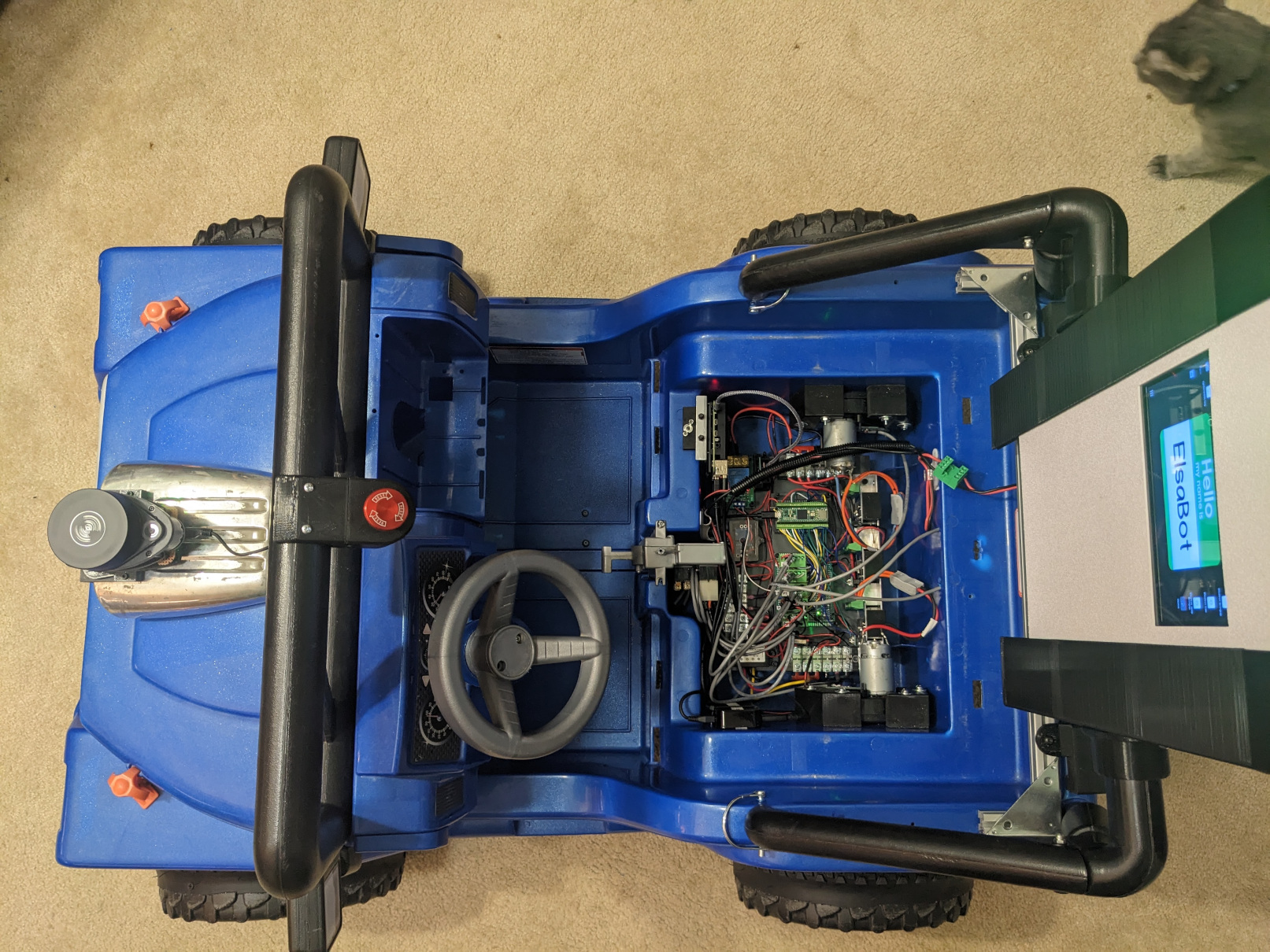
The Elsabot Jeep base:
Phase 1
- Used PowerWheels Jeep chassis
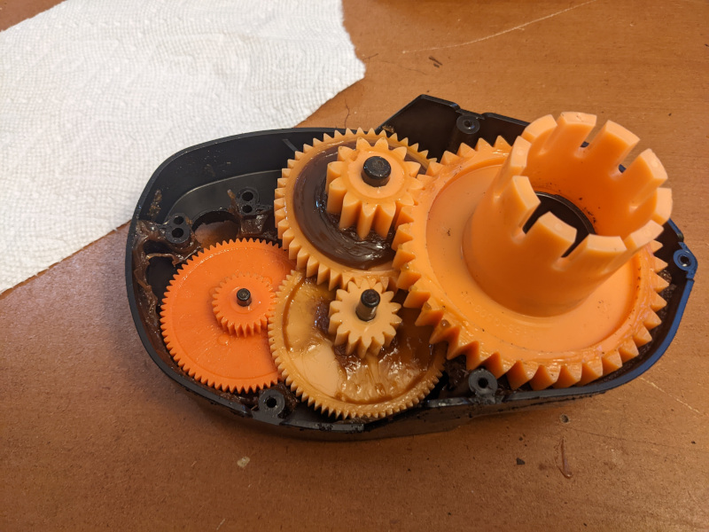
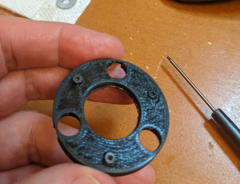
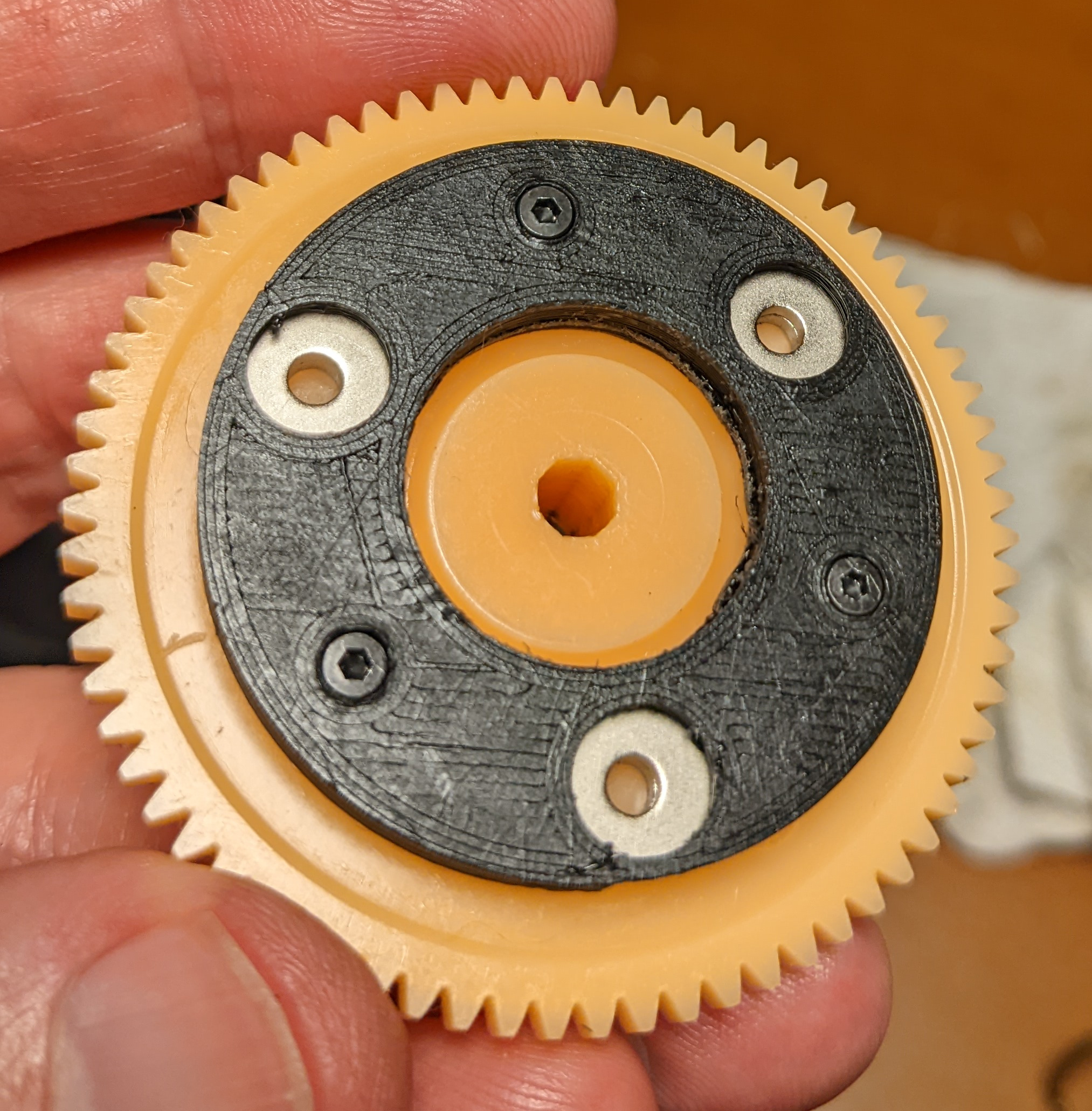
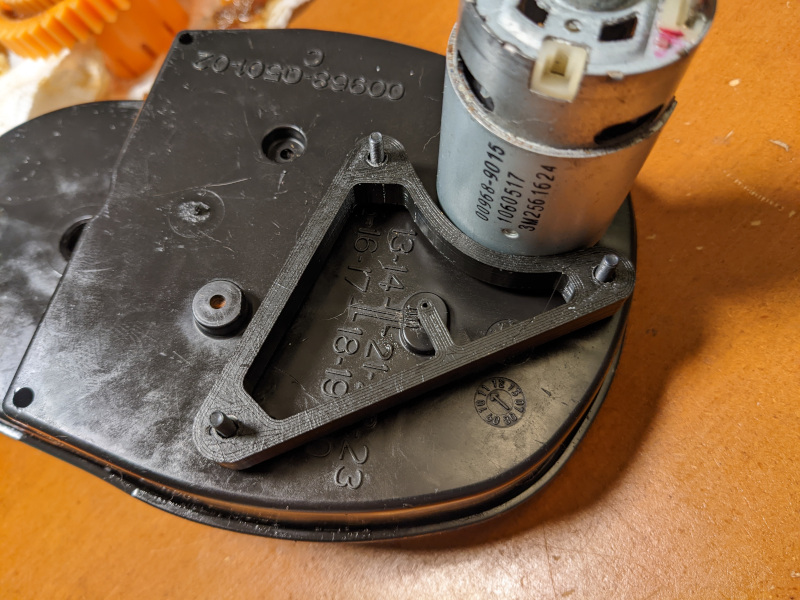
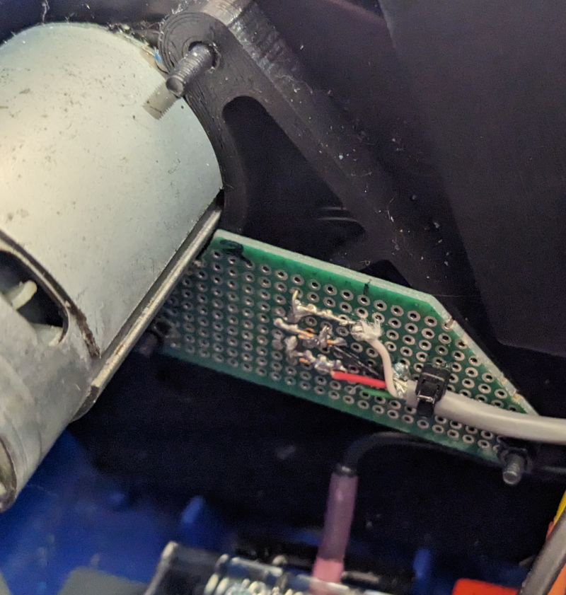
- Existing rear 12V gearbox motors modified with magnets and a Hall sensor for measuring rotational speed
BTS7960 motor driversNow using RoboClaw 2x30A DC Motor driver- Front steering modified to use PowerWheels steering motor.
- Steering shaft cut with encoder mounted to sense steering wheel rotation, and encoder mounted underneath to measure steering rod movement.
- GY85 IMU
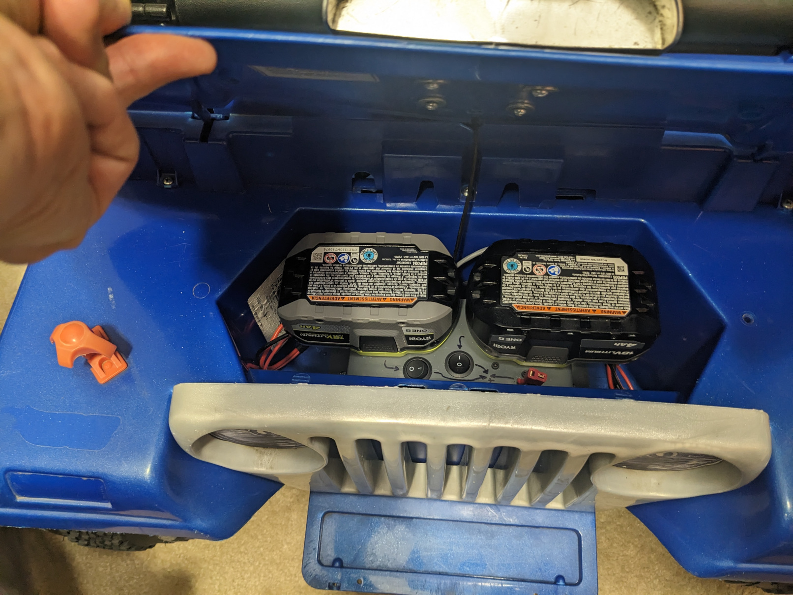
- 2-18V Ryobi batteries: 1 for uC and CPU and 1 for powering motors
- 2-INA226 power monitor ICs
- Teensy 4.1 uC
- 4 port USB hub
- Motor power relay controlled by emergency switch, 433 MHz remote controlled relay, and uC
- RPLidar A1
- 2-HCSR04 ultrasonic range sensors (back mounted)
- RPi4
- DC-to-DC converter for control circuitry
- Functionality
- Game controller control
- Driver (kid) control
- ROS Nav2 navigation
Phase 2 (WIP)
- Seeed odyssey j4125 CPU
- OAK-D camera with and pan and tilt servos
- Display panel
- USB speaker
- Seeed ReSpeaker USB Mic Array
- Various DC-to-DC converters
- 10-port USB hub
- GPS
- Functionality
- Same as phase 1
- Interactive functionality using Camera AI and voice control (as for previous projects)
Currently using micro-ROS for ROS Humble.
See this project for the ROS2 bring-up scripts and ROS packages used: https://github.com/rshorton/elsabot_jeep
- Be sure that your firmware build uses the provided micro-ROS meta configuration file (micro_ros.meta) otherwise startup will fail due to insufficient micro-ROS related resources.
- Press and hold the game controller LT button (front left bottom) to use teleop control via controller joysticks. This will also overide navigation control.
- Press and hold the game controller LB button (front left top) to enable driver control using accel pedal and steering wheel.
- Press the X (slow), A (normal), B (ludicrous) buttons to set the maximum speed for manual control.
YouTube Videos
More pictures
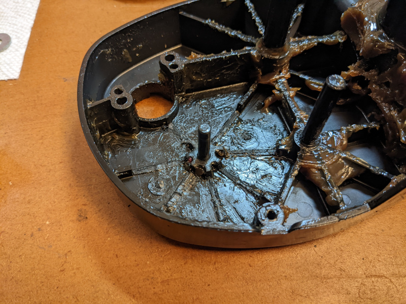
Magnets were mounted on the second transmission gear and a Hall Sensor was mounted on the outside of the motor.
This provides space for the magnets and mounting bracket.
Neodymium magnets: 0.375" OD x 0.06" thick, 2 magnets per position
