This is an earnest attempt at writing a renderer for 4D geometry and physics engine for 4D objects, written for learning both wgpu-rs and 4D geometry.
I gave a talk about this project! You can watch the talk here: https://www.youtube.com/watch?v=_22oxXEX_xc&t=717s
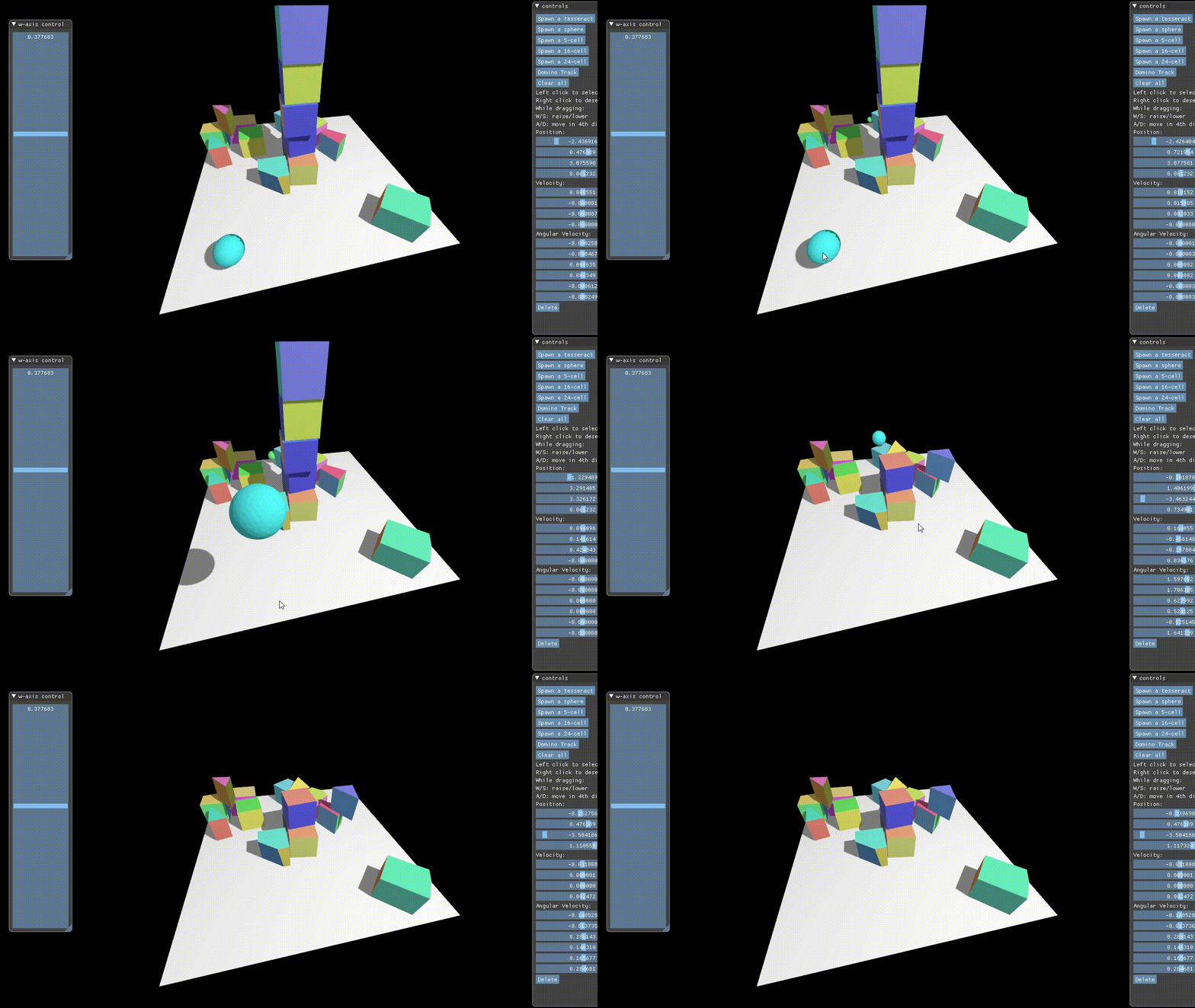
Knocking over a stack of tesseracts with a hypersphere:
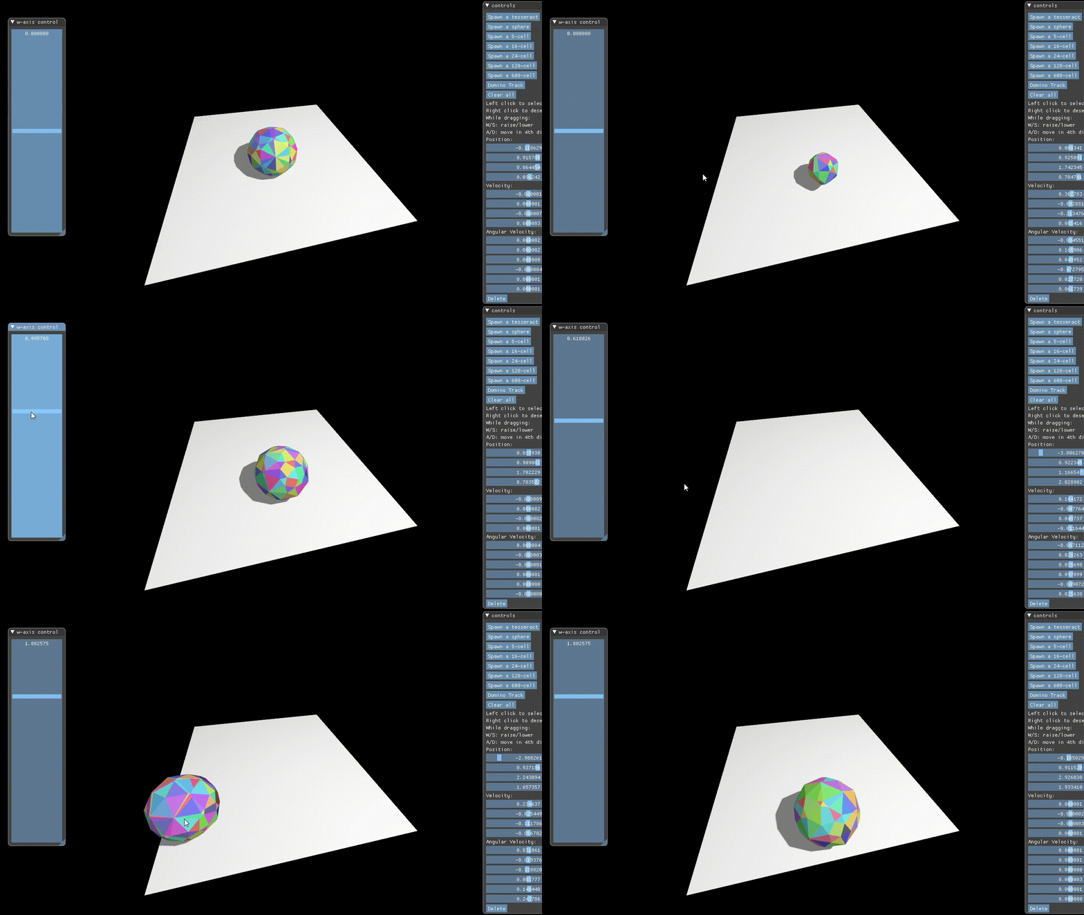
Rolling a 600-cell (a 4D Platonic "solid" composed of 600 tetrahedral cells, the
equivalent of faces in 4D) around:
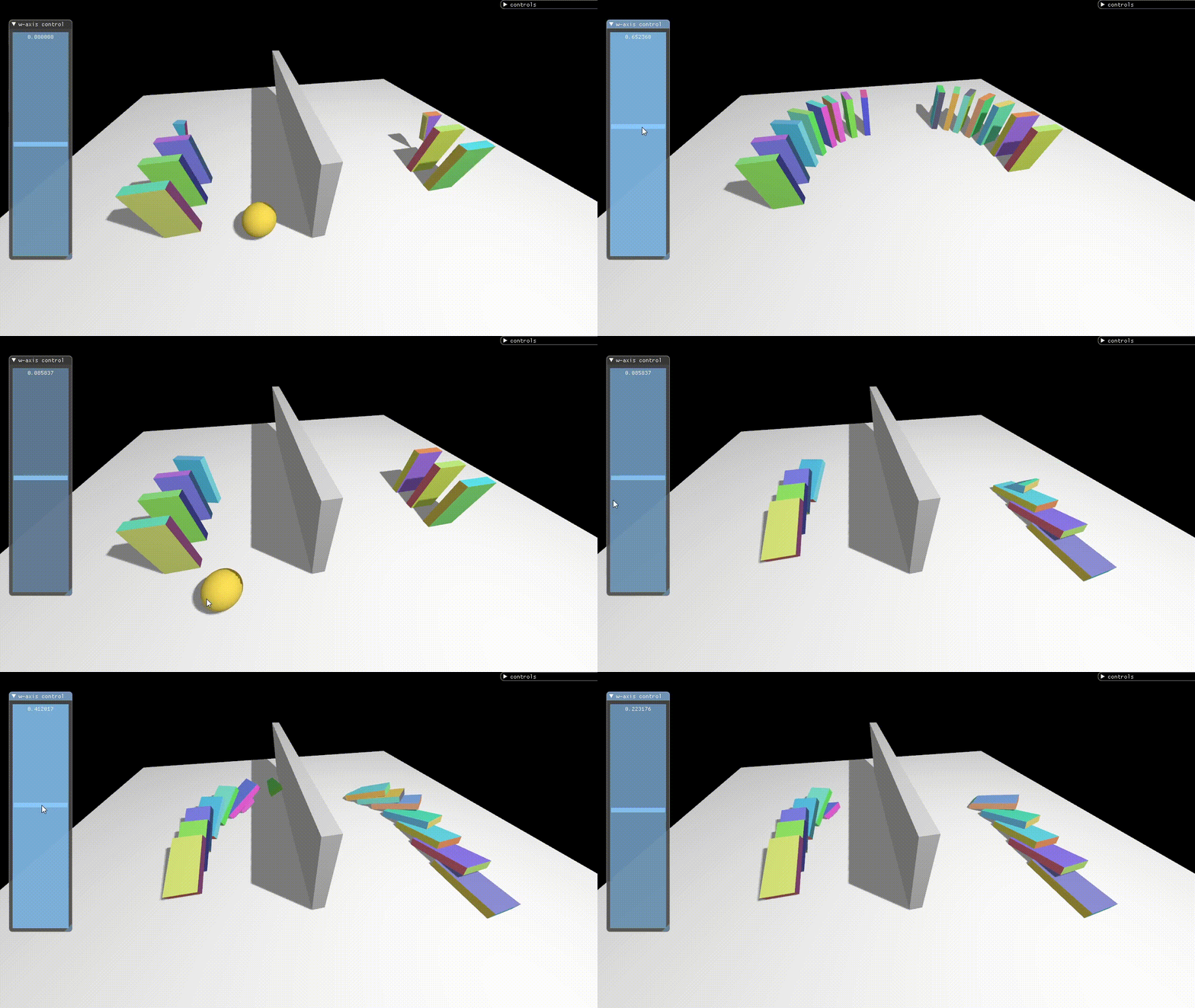
A domino track that appears to go "through" a wall, but in actuality goes around
it in the 4th dimension:
This project was largely motivated by seeing Marc ten Bosch's games, Miegakure (still in development at the time of writing) and 4D Toys.
While there have been many implementations of 4D visualisers, I've not come across an implementation or a good description of or even general pointers to how to implement a physics engine in 4D. 4D Toys is the only example of an actual 4D engine I could find, and it's closed-source.
This gave me the idea of investigating and attempting to implement a 4D physics engine. How hard could it be, right?
(Marc ten Bosch has published a paper N-Dimensional Rigid Body Dynamics about his 4D physics engine, but by this point most of my implementation was in place and it would've been helpful to be able to refer to this earlier on...)
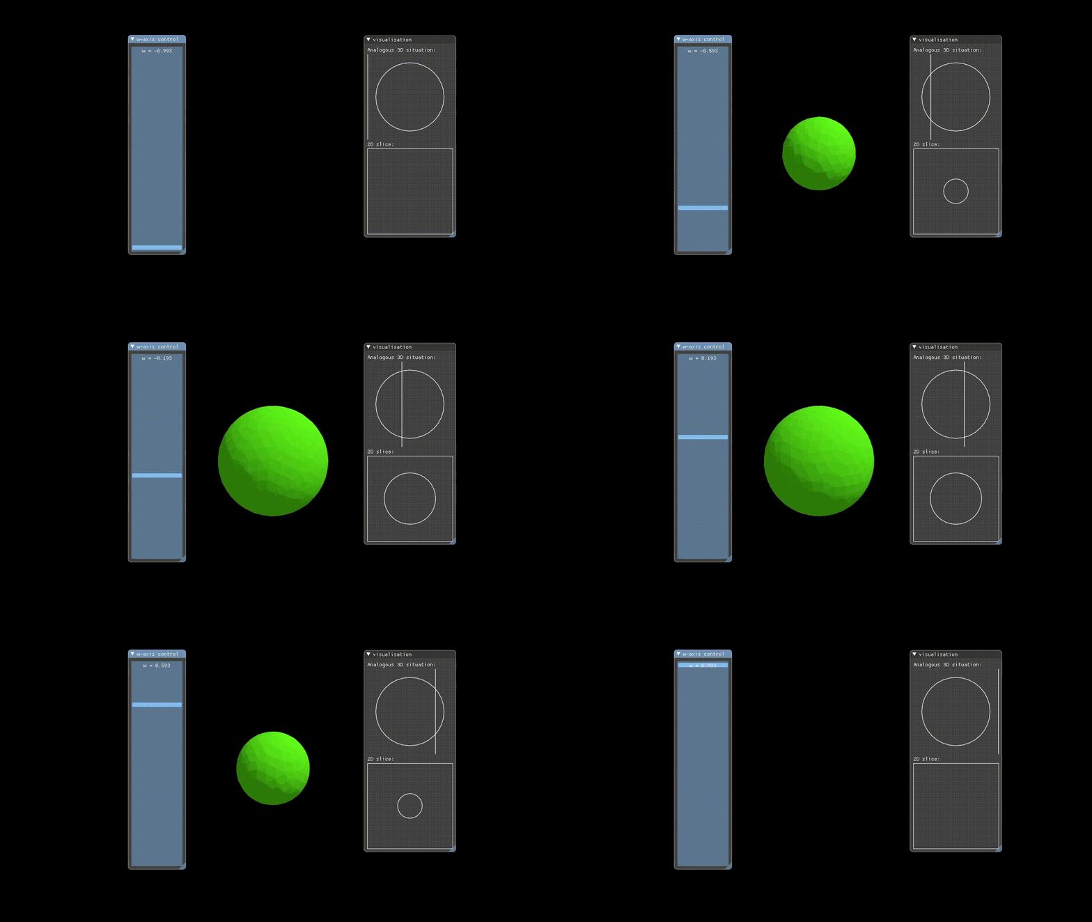
Hypervis implements rendering of 4D objects by only rendering a 3D slice of the 4D space to the user. The X, Y, and Z-axes have their conventional meanings, but in addition to these the user manually controls which W-axis slice is rendered via a slider. This means that we are showing incremental hyperplanar slices through the 4D space.
Just like how in 3D, the surface of an object is represented in a mesh of triangles, in 4D the surface of an object would be represented by a mesh of tetrahedra.
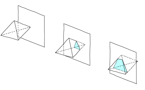
To render this 4D mesh, we intersect it with the current W-slice that we are interested in. Computing an intersection between a hyperplane and a singular tetrahedron is not difficult - we simply apply the standard intersection test for a line and a plane (in its point-normal representation) for each of the edges of the tetrahedron, which gives us 4 possibilities:
- The tetrahedron is parallel to the hyperplane. This is a degenerate case and can be handled by rendering the tetrahedron if it is contained within the hyperplane.
- The tetrahedron is not parallel to the hyperplane, in which case we can
consider the hyperplane of the tetrahedron, which is a 3D subspace whose
intersection with the slice plane is a 2D plane. Thus, we can consider this
as a problem of intersecting a tetrahedron and a 2D plane in 3D space,
giving us 3 possibilities:
- no edges intersect the plane - render nothing
- 3 edges intersect the plane - render a triangle
- 4 edges intersect the plane - render the resulting quadrilateral
It is possible to encode "winding" data for tetrahedra so you can recover the correctly oriented triangles for backface culling, but for simplicity I just emitted two triangles, one in each orientation.
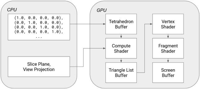
All of this happens on a compute shader (with the help of wgpu-rs!) written to process a mesh of tetrahedra from a "Tetrahedron Buffer", which together with the slice hyperplane returns a regular list of triangles that are passed down the regular rendering pipeline.
For a rigid body physics engine the motion of any body can be described using two components, the linear velocity and the angular velocity. Linear velocity is easy - you simply store the 4D vector corresponding to the direction and speed of motion. Angular velocity is trickier though, because how do you represent rotations in 4D?
When talking about rotations in 3D, we usually reach for a quaternion implementation, but quaternions are specific to rotations in 3D. To express rotations in 4D we need to reach for a field of mathematics called Geometric Algebra.
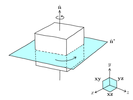
A basic way to conceptualise it is this - in 3D, we tend to think of rotation as happening around an axis, but this is in fact a very 3D-centric view of looking at it. For example, if something is rotating in a 2D space, where is the axis of rotation? It can't exist! A more natural way to consider rotations is that they occur in a particular plane instead:
n represents the axis of rotation, but equivalently the rotation could also be described by taking the dual of n giving us the plane n*. What is n* exactly though? It is an object which in geometric algebra is called a bivector.
Bivectors, like their name suggests, act very similar to normal vectors, but instead of representing a direction and a magnitude we can think of bivectors representing a particular plane and a magnitude. (A bivector also identifies the orientation of the plane as well. If you negate a bivector, you get a bivector representing the same plane and magnitude, but the plane has flipped.) Just like how every vector in 3D is made out of linear combinations of the 3 basis vectors, the unit X, Y, and Z vectors, every bivector in 3D is made out of linear combinations of the 3 basis bivectors, xy (spanning the x and y axes), yz, and xz.
Similar to how we can build quaternions from a scalar plus an imaginary vector, we can build an object called a rotor from a scalar plus a bivector. In fact, quaternions and 3D rotors are isomorphic - they are exactly equivalent, and all operations on them behave exactly equivalently.
So what was the point of defining bivectors and rotors if we end up with the exact same thing as quaternions anyway? Well, quaternions don't generalise to 4D, but rotors do! A rotor in 4D looks like this:
struct Bivec4 {
    xy: f32,
    xz: f32,
    xw: f32,
    yz: f32,
    yw: f32,
    zw: f32,
}

struct Quadvec4 {
    xyzw: f32,
}

struct Rotor4 {
    s: f32,
    b: Bivec4,
    q: QuadVec4,
}
You may notice bivectors in 4D actually have 6 components - this is because there are 6 ways to combine the 4 axes resulting in 6 basis bivectors. In addition to the bivector component there is a quadvector component - this is because N-dimensional rotors are actually elements of the even subalgebra of G(N, 0) and not just the addition of a scalar and a bivector component.
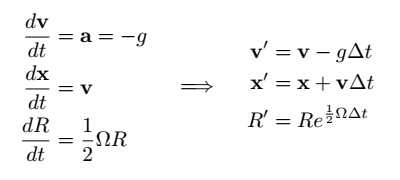
This gives us the following update formulae for rigid body motion:


