Per default the Raspberry Pi is powered via the USB port, but no power switch exists for a controlled shutdown.
This device connects to the GPIO and power pins of the extension port.
An Arduino Tiny (Digispark) controls the 5V supply voltage via an MOSFET switch (up to 3A).
In addition the Arduino
- reads the status of the Raspberry Pi on
GPIO 27. Pulled low while the Raspberry Pi is running, - sets the shutdown request on
GPIO 17in case the button is pressed, - disconnects the 5V supply from the Raspberry Pi after a predefined timeout. This allows for a controlled shutdown and avoids a possible corruption of the SD-card.
The device can be powered by a 5V supply, or a DC-DC converter can be added to allow the powering directly from a 12V (or higher) supply (e.g. car battery). The Arduino is supplied by a 3.3V regulator on the board. This ensures, that the signals of the Arduino and the Raspberry Pi are compatible.
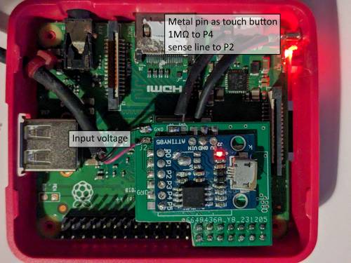
The default power button is a touch button connected via a 1MOhm resistor to Port 4 and sensed via Port 2 of the ATTINY85. A standard button can be connected to Port 4 as well, but requires to adapt the code.
This device has been developped for the powering of a Raspberry Pi 3a used as Wireless access point (installed is RaspAP ) in a very flat case. The Raspberry Pi is used in a Camper Van to connect to camp ground wireless networks or LTE/4G. The device is powered in this case by 12V.

Power switch installed on a Raspberry Pi 3a, including a touch button (metal pin)
The power required by the device, when the Raspberry Pi is switched off, is about 20mW (ca. 1.5mA@12V).
- Arduino Tiny - Digispark board. The version with the micro USB port is preferred. This allows to program the board while soldered to the PCB.
- DC-DC converter in case the the input voltage is higher than 5V.
- PCB and the required components (SMD components and a pin header)
- MOSFET transistor
- Suitable types: FDN360P, TMS2305, DMT3098 (package: SOT-23). All allow to switch up to 2A continuously, which should still be fine for a Raspberry Pi 4.
- For higher currents an IRF9310 (up to 16A) could be used, but this comes in a different package (SO-8) and the layout has to be changed accordingly.
The Arduino IDE is used for the programming of the Arduino Tiny. See the header of the program file for more details of the program flow.
The package CapacitiveSensor is required, if the above mentioned touch button is used.
On the Raspberry Pi side, you need to add the following lines to /boot/config.txt
# Request shutdown by setting GPIO 17 to HIGH
dtoverlay=gpio-shutdown,gpio_pin=17,active_low=0,gpio_pull=down
# GPIO 27 flags the shutdown of the system
gpio=27=op,dl
Schematic and board design are available in the Autodesk EAGLE format. The library file contains the non-standard components (Arduino Tiny, DC-DC converter). Gerber files, Bill of material and placement files are available as well.
The board connects to the first 14 pins of the extension port of the Raspberry Pi via a pin header. The header connector is installed to the bottom of the board. A low profile connector is recommended. For the Raspberry Pi 3a in its default case, the pins had to be shortened a bit and a header with a height of only 8.6mm has been used.

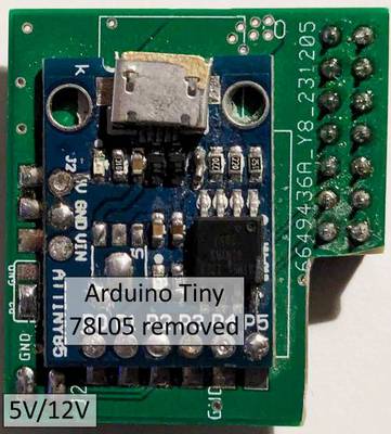
Arduino Tiny soldered to the Power Switch board
The design of the board is somewhat special, because a very flat layout is needed to fit into a standard case.
Therefore the Arduino Tiny is soldered to large SMD pads. This is not difficult, but requires some soldering experience. It might help to solder a solid wire (0.4mm) to the through holes of the
Arduino Tiny, bend the wires by 90° to the outside, cut to length and solder the ends of the wires to the SMD pads.
Before soldering, add an isolating tape to the bottom of the Arduino to avoid shorts.
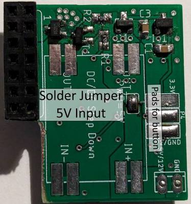
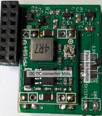
On the bottom side of the board a solder jumper sets the source of the power. A closed jumper connects the input voltage from the pin header directly to the Raspberry Pi and the on board regulator. For higher voltages, e.g. 12V from a car battery, the jumper should be left open and a mini DC-DC converter is soldered to the SMD pads on the bottom side. The output voltage of the DC-DC converter should be set to 5V. Again add an isolating tape to the bottom of the DC-DC converter to avoid shorts.


Bottom side of the Power Switch: left side for 5V input voltage with the solder jumper closed. On the right side the DC-DC converter is installed for a higher voltage
On the bottom side you find in addition 3 solder pads to connect a button. One of the pads carries either the signal of Port 2 or ground. This can be selected by the solder jumper on the top.
- Passive button: connect to Port 4 and the P2/GND pad and select GND with the solder jumper on the top.
- Software based touch button: connect to P4 and P2 (select P2 with the solder jumper on top).
- Hardware touch button: signal connected to P4. Powering by 3.3V and GND pad.
The software based touch button is implemented in the code. The other options require an adaption of the code.
The Arduino Tiny will draw up to 10mA when powered by the onboard 5V regulator (78X05). This is mainly due to the quiescent current of the regulator itself , the power LED and the 1.5kOhm pull-up resistor connected to port 3 of the ATTINY85 (needed for the USB programming). The ATTINY85 with reduced frequency of about 1MHz utilizes only a few hundred micro Amps.
Reduce the required power by
- run the ATTINY85 at a low frequency (e.g. 1MHz)
- use an external 3.3V regulator with low quiescent current (here MCP1703). Remove the 78X05 from the board (might not be necessary).
- either remove the power LED, or change at least the series resistor from 1kOhm to 10kOhm
- remove the LED attached to Port 1, or increase the series resistor to 10kOhm
- disconnect the 1.5kOhm resistor from the power rail of the ATTINY85 and connect it to the USB 5V line (USB connector side of the corresponding Schottky diode).
For a 5V powered system, this should bring the qiescent current down well below 1mA at 5V. With the installed DC-DC converter the current stays at about 1.5mA at 12V (18mW).