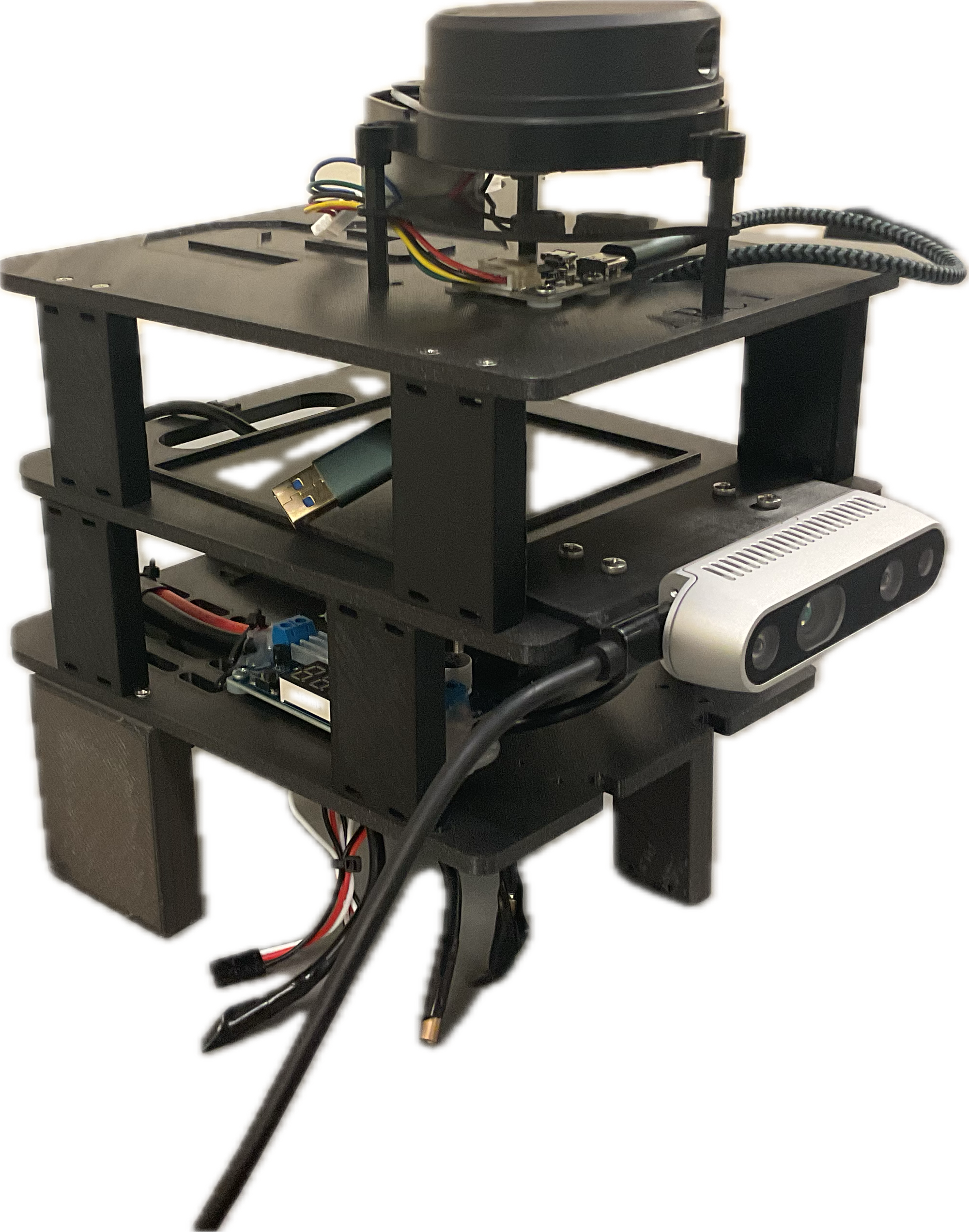
Author: xinliangzhong ([email protected])
This repository can calibrate both lidar and radar with a camera. However, for this test, calibration was only performed between the lidar and the camera. For radar-camera calibration, please refer to the original repository(#).
- Camera: Intel RealSense D435i
- Lidar: YDLIDAR X4PRO (2D)
- Ubuntu 16.04 LTS (tested on this specific version)
- ROS Kinetic
- OpenCV 3
- Ceres Solver
To get started, you need to set up your environment. The requirements include Ubuntu 16 and ROS-Kinetic. To simplify this process, you can use a Docker container by running the following command:
xhost +local:docker
docker run -it --rm \
    --name ros_kinetic_gui \
    -e DISPLAY=$DISPLAY \
    -v /tmp/.X11-unix:/tmp/.X11-unix \
    -v $HOME:/home/$USER \
    ubuntu:16.04 bash -c "
    apt-get update && apt-get install -y curl gnupg2 lsb-release && \
    echo 'deb http://packages.ros.org/ros/ubuntu xenial main' > /etc/apt/sources.list.d/ros-latest.list && \
    curl -s https://raw.githubusercontent.com/ros/rosdistro/master/ros.asc | apt-key add - && \
    apt-get update && apt-get install -y ros-kinetic-desktop-full && \
    echo 'source /opt/ros/kinetic/setup.bash' >> ~/.bashrc && \
    bash"
Next, you need to install Ceres Solver. Use the command below:
sudo apt update
sudo apt install -y cmake libgoogle-glog-dev libgflags-dev libeigen3-dev libsuitesparse-dev
Place the extracted package into a ROS workspace and compile it using the following command:
catkin_make --pkg camera_laser_calibration
Go to your ROS workspace:
source devel/setup.bash
As part of the calibration process, you need to provide your camera's intrinsic and distortion parameters. These values must be added to the configuration file located at ./config/config.yaml.
- fx: Focal length in the x-axis.
- fy: Focal length in the y-axis.
- cx: Principal point x-coordinate.
- cy: Principal point y-coordinate.
The intrinsic matrix can be represented as:
K = [ fx  0  cx ]
    [  0  fy  cy ]
    [  0   0   1 ]
Intrinsic calibration also helps determine the scale of the image and corrects for any imperfections in the camera's optical system, such as skew.
- k1: Radial distortion coefficient 1.
- k2: Radial distortion coefficient 2.
- p1: Tangential distortion coefficient 1.
- p2: Tangential distortion coefficient 2.
Ensure these parameters reflect your specific camera setup to achieve accurate calibration.
Then run:
roslaunch camera_laser_calibration collect_laser_image_data.launch image_topic:=PATH_TO_YOUR_DATASET
Navigate to the directory of the bag file you want to use for calibration and execute:
rosbag play --pause XXX.bag
Use the spacebar to control the playback and pause of the bag file.
Open a new terminal and start rqt.
Select Plungs/Configuration/Dynamic Reconfiguration.
Finally, you will see the following two screens in rviz and rqt, indicating success. In rviz, images and laser-colored lines appear, and in rqt, the control interface is displayed.
And also it is extracting the intrinsic value of the camera
There is a demonstration video How_to_use.mp4 in the root directory and also we have a textual explanation:
Pause the bag playback.
Use the 2D Nav Goal tool in the rviz toolbar to select laser/scan points. Once selected, the terminal where the calibration program was initially started will display output similar to the following:
[ INFO] [1534164489.163120940]: Setting goal: Frame:laser, Position(**1.575, -0.752**, 0.000), Orientation(0.000, 0.000, -0.688, 0.725) = Angle: -1.518
Copy the highlighted portion to the clipboard.
Switch to the rqt interface and paste it into the box next to laser_coor. For the above example, after pasting, it should display 1.575, -0.752.
Check the Save button.
At this point, the image corresponding to the current laser will pop up. You need to draw a small rectangle. After completing the selection, a feature point corresponding to the coordinate point will be detected and displayed. Then, press the spacebar in the image window. The window will close, and the data will be automatically saved in the data/data_v2.txt folder in the format x y u v.
Calibration:
Copy the data/data_v2.txt file and rename it to data.txt.
roslaunch camera_laser_calibration calibration.launch image_topic:=PATH_TO_YOUR_DATASET
Calibration result:
Tcl: The result is the extrinsic parameters from the lidar to the camera, which will be automatically saved in the `data` folder.
For extrinsic calibration, you need to define the transformation from the camera to the 2D LiDAR. This transform specifies the spatial relationship between the two sensors and is critical for aligning their respective data streams. The transformation is typically represented as:
- Rotation Matrix (R): Defines the orientation of the camera relative to the LiDAR.
- Translation Vector (t): Specifies the position of the camera relative to the LiDAR.
In this case, we are working with the camera-to-LiDAR transformation, which aligns the coordinate systems of a camera and a LiDAR sensor. This is crucial for sensor fusion tasks, allowing 3D LiDAR data to be matched with 2D images from the camera. The transformation is represented by a 4x4 matrix:
T=[R 0]
  [t 1]


